headline bars
continuation tabs
notes
warnings
headline bars
continuation tabs
notes
warnings
headline bars
continuation tabs
notes
warnings
19
OPERATING INSTRUCTIONS
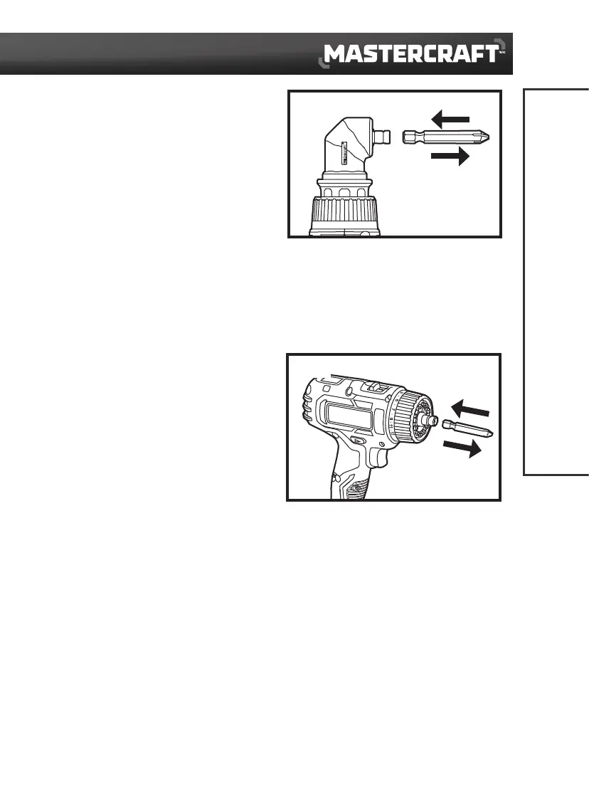
INSTALL A BIT INTO THE RIGHT-ANGLE
ADAPTOR
(fig 13)
1. Lock the variable-speed trigger switch by placing
the direction-of-rotation selector in the OFF
(centre) position.
2. Insert a suitable bit into the hex chuck on the
right-angle adaptor as far as it will go. Then the
bit can be tightened by the magnetic force in the
hex chuck.
REMOVE A BIT FROM THE RIGHT-ANGLE
ADAPTOR
(fig 13)
1. Lock the variable-speed trigger switch by placing the direction-of-rotation selector in the OFF
(centre) position.
2. The bit can be easily pulled out from the hex chuck on the right-angle adaptor.
INSTALL A BIT INTO THE DRILL/DRIVER
(fig 14)
1. Lock the variable-speed trigger switch by placing
the direction-of-rotation selector in the OFF
(centre) position.
2. Insert a suitable bit into the hex chuck on the
drill/driver as far as it will go, then the bit can be
tightened.
REMOVE A BIT FROM THE DRILL/DRIVER
(fig 14)
1. Lock the variable-speed trigger switch by placing the direction-of-rotation selector in the OFF
(centre) position.
2. The bit can be easily pulled out from the hex chuck on the drill/driver.
fig 13
Remove
Install
fig 14
Install
Remove