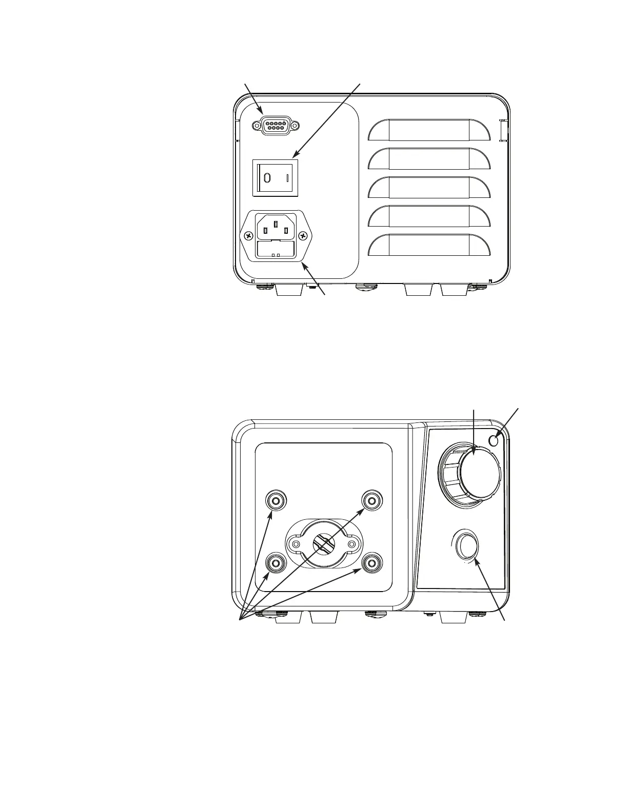
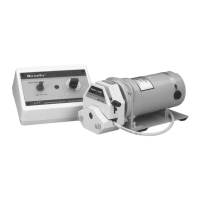
A. IEC Power Entry module
B. Power Switch
C. External Start/Stop Connector
Figure 2-1. View of Rear Drive
Pump Drives Operating Manual 2-2Masterflex
Section 2
Installation and Setup
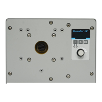
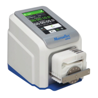
A. Pump Head Mounting Holes
B. 1-Turn Speed Control
C. Power Indicator
D. Direction Switch
Figure 2-2. View of Drive Front Controls
A
B
C
A
B
C
D