ASSEMBLY INSTRUCTIONS
The Bench Grinder is provided with a left and
right two piece Tool Rest. Right Tool Rest has
a at, smooth surface to lay your workpiece
against. Left tool rest is used to sharpen twist
drill bits.
1. DO NOT assemble the Bench Grinder until
you are sure the tool IS NOT plugged in.
2. DO NOT assemble the Bench Grinder until
you are sure the power switch is in the “OFF”
position.
3. DO NOT assemble the Bench Grinder until
you are sure the grinding wheels are rmly
tightened to the Bench Grinder.
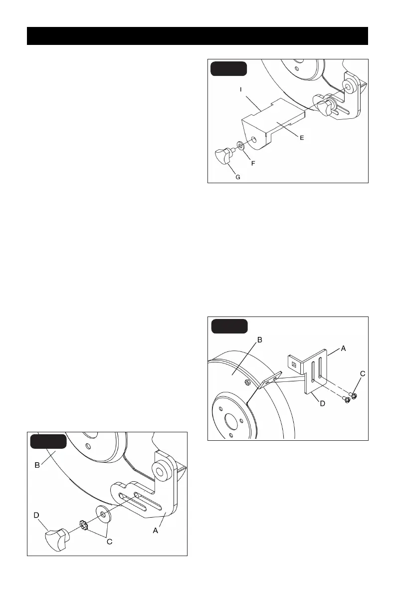
TOOL RESTS (Figs. E and F)
The Bench Grinder is provided with two
dierent Tool Rests assemblies. The Left Side
Tool Rest is grooved to accept drill bits. The
Right Side Tool Rest is entirely at.
1. Assemble the Tool Rest Supports (A) to the
inside surface of the Wheel Covers (B) with
the at and lock washers (C) and knobs (D)
as shown. See Figure E.
2. Assemble the Tool Rests (E) to the
Supports (F) with the at washers (G) and
Adjustment Knobs (H) as shown. See
Figure F.
3. Adjust each Tool Rest until its inside edge
(I) is 1/16” from the grinding wheel. Firmly
tighten the knobs holding the supports. See
Figure F.
SPARK ARRESTORS (Fig. G)
1. Assemble the Spark Arrestors (A) to the
front surface of the Wheel Covers (B) with the
at washers and pan head scre ws (C) as
shown. See Figure G.
2. Adjust each Spark Arrestor until the lower
edge (D) is 1/16” from the grinding wheel.
Firmly tighten the hex head screws. See
Figure G.
FIG. E
FIG. F
FIG. G
Page 11