Components included
Head unit Surface
mount bezel
Bayonet collar
MasterBus cable*
(6m / 20ft)
MasterBus Terminator*
4 × Phillips
countersunk
self-tapping
screws (2.9×16)
If you are not knowledgeable about electrical
systems, have an electrical professional install this
unit.
WARNING
The SmartRemote is not waterproof. Do not install
where the display is exposed to water.
CAUTION
The Mastervolt product warranty covers the
SmartRemote for the first two years after the
purchase date.
The warranty is limited to the cost of repair and/or
replacement of the product. Costs of labor or
shipping are not covered by this warranty.
Mastervolt cannot accept liability for damage due to
the misuse of the SmartRemote.
Warranty
Contact your local waste disposal depart-
ment to properly dispose of the unit.
EMEA
Snijdersbergweg 93
1105 AN AMSTERDAM
The Netherlands
+31 (0)20 34 22 100
info@mastervolt.com
ASIA/PACIFIC
42 Apollo Drive, Rosedale
AUCKLAND 0632
New Zealand
+ 64 9 415 7261
enquiries@bepmarine.com
NORTH AMERICA
N86 W12500 Westbrook Crossing
Menomonee Falls, WISCONSIN 53051
USA
+1 800 307 6702, Option 1
technical@marinco.com
Correct Disposal
The three push buttons P1, P2 and P3 provide a
scroll and select function. Their behavior depends
on the connected device.
When multiple devices are connected, first select
the required device.
When idle, the button menu slides down. To get it
back, press any button.
To enter the main menu, simultaneously press P1
and P3 for 5 seconds.
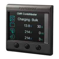
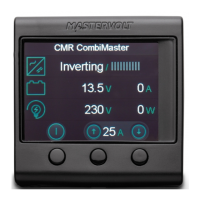
The simple and intuitive screens speak for
themselves. For example when monitoring an
inverter or charger:
Press P1 to switch the inverter on or off.
Press P2 or P3 to adjust the power sharing level.
Operation Notes
For additional information, like supported devices,
please visit our website: www.mastervolt.com
Specifications
Mastervolt CZone Drop Cable*
(1m / 3.3ft)
SmartRemote
QuickStart Installation Guide
* Need to be ordered separately with OEM packaging
10000015712/02
P1 P2 P3
Model:
Product code retail:
Product code OEM:
Dimensions:
Screen:
Weight:
Operating temperature:
Relative humidity:
Storage temperature:
Power supply:
Power consumption:
Protection degree:
Approvals:
Interfaces:
SmartRemote
77010600
77010500
72×72×30 mm/2.8×2.8×1.2"
320x240 pixels,
16 bits color, 2.8"
75 g / 2.6 oz
-20 to 55°C/-4 to 131°F
max. 95% non-condensing
-30 to 70°C/-22 to 158°F
bus powered, 11-14V
<180mW (idle mode)
IP20
CE
MasterBus,
CZone (upcoming)
To download this guide in other languages,
please visit our website: www.mastervolt.com