Rev. Descrizione Redatto/Gestito Approvato Cod.Ident. Pagine Data Em.
0.6 Manuale Istruzioni GN UTEC B041.M01.EN 10/47 07/2014
closing of the protection door.
Active safety devices are the devices or solutions which eliminate or reduce the
risks to the operator and require active and conscious intervention by the operator
for the preventive action to be carried out.
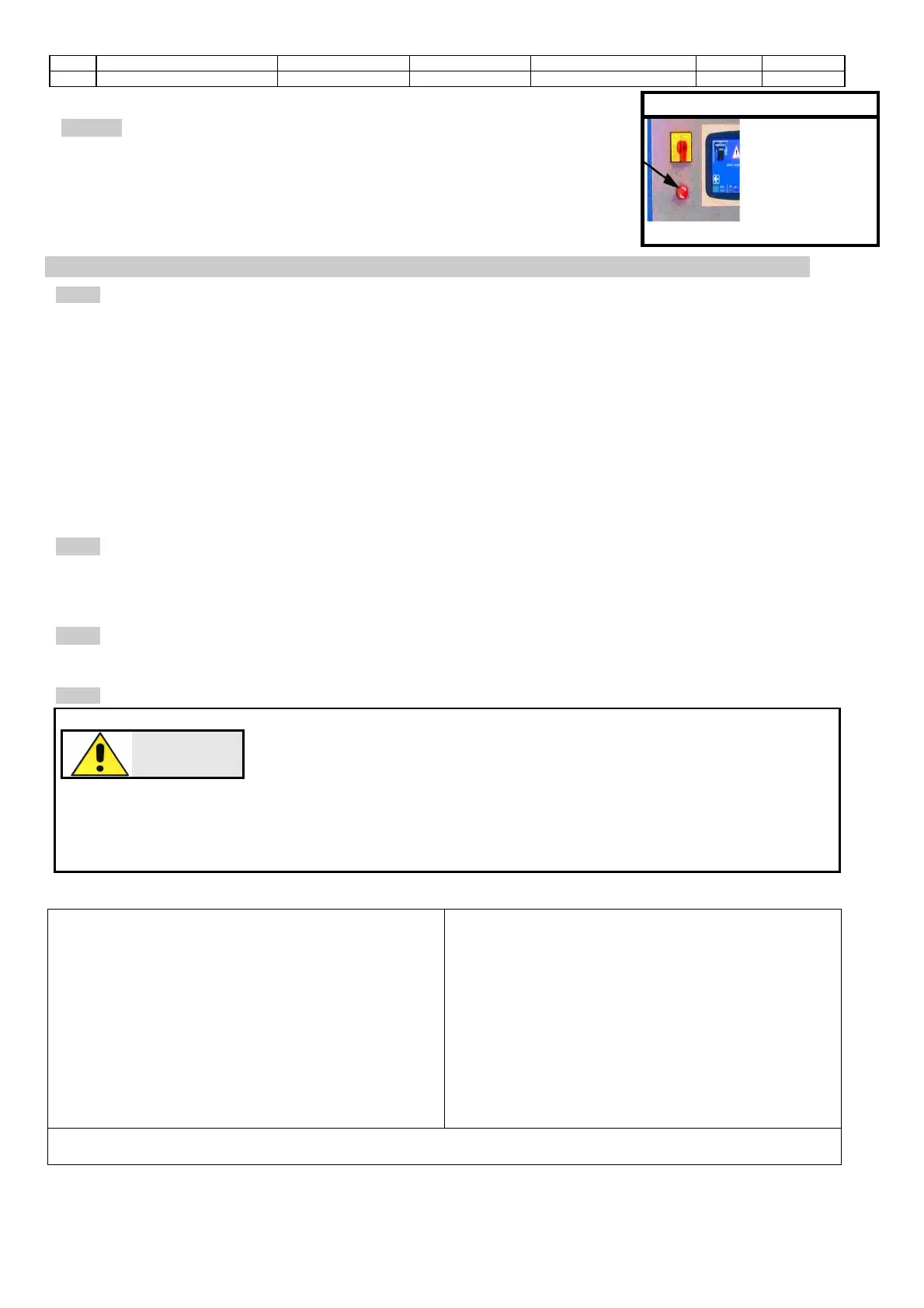
The appliance is equipped with a main switch acting also as emergency switch. By
activating it (Fig.7), stops moving.
Picture
. 7
INSTALLATION INSTRUCTIONS
The equipment must be placed in an ideal position and environment for the use it has been conceived for
(laboratory use and protected from atmospheric agents) and that the machine is placed by a qualified operator.
+5°C / +40°C
ALLOWED RELATIVE HUMIDITY:
30% / 70%
GENERAL ADVICE
• The machine must be installed in an area which allows ease of access to all parts so that maintenance
may be carried out.
• Unauthorised people and objects which could be potential sources of danger must not be permitted in the
area surrounding the machine.
Do not position the equipment near instruments or appliances which could produce vibrations.
EN Standad requires the machine to be rigidly mounted on a firm and level concrete base. The levelling foot
supplied are considered acceptable for mounting on any firm and rigid level surface
TRANSPORTATION AND MOVEMENT
These instructions are applicable to the machine assemblers. Ensure the equipment is correctly supported at the
lifting point and that the machine does not slip. Do not remain in direct line with the application of force and do not
allow personnel where there are loads that cannot be adequately supported by mechanical means.
After removing the package, check that any parts of the machine are not damaged. In case of doubt, DO NOT
USE THE MACHINEand ask the manufacturer.
DANGER
Wiring of the electrical system must be carried out by qualified personnel.
Before wiring consult the electric plan linked to the instructions manual and the
registration plate on the machine for information regarding supply, frequency and
nominal current. Connect the earthing system via the PE terminal (yellow-green)
before any other connection.
Apply a knife switch at the top of the connecting cable of the machine to the power system.
The knife switch must be combined with a safety device against the overload with a differential switch (safety
switch).The technical features of
the safety device must be in accordance with the standards in force in the
country where the machine has been installed.
ELECTRIC TOLERANCES:
• Frequency: ± 1 % of the nominal one
in a continuous way
± 2 % of the nominal one for a short period
• The harmonic distortion of the sum from the second
to the fifth harmonics not more than 10 % of the total
voltage as a real value between the conductors. A
further distortion of 2% is accepted for the sum from
the sixth to the thirtieth harmonics of the real total
value between the conductors.
• With reference to the voltage imbalance of the three-
phase voltage, the inverted sequence component and
the zero sequence component must not be more than
2% of the direct sequence component of the voltage.
The voltage pulses must not last more than 1,5 ms
with an up/down time between 500 ms and 500 ms
and a peak value not higher than 200 % of the real
value of the nominal tension.
• The electric supply must not be interrupted or
zeroed for more than 3 ms at any time. Between
two interruptions it must not take more than 1 s.
• The interruptions must not overcome 20 % of the
tension peak for more than one cycle. Between two
interruptions it must not take more than 1 s.
The manufacturer assumes no liability for any damages to people, things and animals caused by the non-
compliance of the above instructions.
 Loading...