EasyManua.ls Logo

Matrix Endurance Series - User Manual

Matrix Endurance Series
29 pages
Print Icon
To Next Page IconTo Next Page
Loading...
PRODUCT
OWNERSHIP
Question and Answer IconNeed help?

Do you have a question about the Matrix Endurance Series and is the answer not in the manual?

Summary

Cardio Equipment Maintenance

Treadmill Belt Adjustments

Instructions for adjusting treadmill belt tension and alignment.

Treadmill Belt Alignment

Steps for aligning the treadmill belt using roller bolts.

Group Training Equipment Maintenance

S-Drive Belt Adjustments

How to adjust S-Drive belt tension and alignment.

Strength Equipment Maintenance

Ultra Cable Tensioning

Procedure for tensioning cables on Ultra strength equipment.

Versa and Aura Cable Tensioning

Steps for tensioning cables on Versa and Aura equipment.

Aura Belt Tensioning

Instructions for tensioning Aura belts using fold over or barrel clamps.

Overview

This document, "PRODUCT OWNERSHIP," provides essential information for the maintenance and adjustment of Matrix fitness equipment, emphasizing that these procedures are part of normal ownership or leasing and are not covered by warranty or considered equipment defects. It covers cardio, group training, and strength equipment.
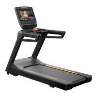
Cardio Equipment

Leveling Equipment:

  • Treadmills (7 & 5 Series): Requires an 8 mm Allen socket and ratcheting wrench. Leveling involves removing shims from the rear foot, loosening bolts, and reinserting shims between the frame and foot.
  • Other Treadmills: Requires a medium-size adjustable wrench. Leveling feet are adjusted counterclockwise from an all-the-way-up position, and then jam nuts are tightened.
  • Climbmills (Performance, Endurance & 7, 5, 3 Series): Requires a 6 mm Allen socket and ratcheting wrench. Leveling feet are adjusted with an Allen socket after removing the dust tray and control zone (Performance & 7, 5 Series) or end caps (Endurance & 3 Series).
  • Climbmills (Lifestyle): Requires tipping the unit forward to expose and adjust leveling feet.
  • Ascent Trainers & Suspension Ellipticals (Performance, Endurance & 7, 5, 3, 1 Series): Requires a 6 mm Allen socket and ratcheting wrench. Leveling feet are adjusted with an Allen socket and wrench.
  • Ascent Trainers & Suspension Ellipticals (Lifestyle): Requires tipping/lifting the unit to a side/front while an assistant adjusts the leveling feet.
  • Upright, Hybrid & Recumbent Cycles (Performance, Endurance & 7, 5, 3 Series): Requires a 6 mm Allen socket and ratcheting wrench. Leveling feet are adjusted with an Allen socket and wrench.
  • Upright, Hybrid & Recumbent Cycles (Lifestyle): Leveling feet are adjusted by hand, then the locking mechanism is engaged.
  • Stepper (Endurance & 7, 5, 3, 1 Series): Requires a medium-size adjustable wrench. Leveling feet are adjusted by hand while tipping the stepper, then jam nuts are tightened.

Treadmill Belt Adjustments:

  • Tools Needed: 8 mm Allen socket and ratcheting wrench, 8 mm Allen T-handle wrench.
  • Tensioning: The two 8mm hex bolts in the end caps adjust the rear roller position. Turning both clockwise adds tension; counterclockwise removes tension. Adjust in 1/4 to 1/2 turns, keeping the belt centered. Tension should be checked monthly.
    • Testing: Press "Go," adjust speed to 3mph / 4.8kph, and stomp on the belt. If it stops, add tension (1/4 turn clockwise to both bolts) and retest.
  • Alignment: To center the belt, turn the bolt on the side the belt moved clockwise. For example, to move the belt right, turn the left bolt counterclockwise. 1/4 - 1/2 turns will significantly move the belt.
    • Testing: Walk on the belt and observe if it drifts. Adjust as needed.

Group Training Equipment

Leveling Equipment:

  • Rowers: Requires a medium-size adjustable wrench. Leveling feet are adjusted by hand, then jam nuts are tightened.
  • Training Cycles: Requires a medium-size adjustable wrench. Leveling feet are adjusted by hand, then jam nuts are tightened.
  • S-Drive Performance Trainer: Requires a medium-size adjustable wrench. Leveling feet are adjusted to ensure the unit is not resting on the front wheels, then jam nuts are tightened.
  • S-Force Performance Trainer: Requires a medium-size adjustable wrench. Leveling feet are adjusted with the transport wheel mechanism up, then jam nuts are tightened.

S-Drive Belt Adjustments:

  • Tensioning: The running belt should not slip at maximum resistance. The two 8 mm hex bolts in the end caps adjust the rear roller position. Clockwise turns add tension; counterclockwise turns remove tension. Adjust in 1/4 to 1/2 turns, keeping the belt centered.
    • Testing: Set both brake controls to maximum resistance. Push the belt (sled position) using the lower handlebars. If the belt slips, add 1/4 turn of tension to the rear roller bolts and repeat.
  • Alignment: To align the belt, turn the bolt on the side the belt moved clockwise. For example, to move the belt right, turn the left bolt counterclockwise. 1/4 - 1/2 turns will significantly move the belt.
    • Testing: Walk on the belt and observe if it drifts. Adjust as needed. Check tension after aligning.
  • Lubrication (S-DPT-01/TM529 ONLY): S-DriveP/TM535, S-DriveM/TM534, & S-DriveC/TM533 do not require lubrication. The TM529 has an unwaxed deck and belt, requiring lubrication every three months (depending on usage).
    • Checking Lubrication: With both brake levers at maximum, stand at the top of the deck. Adjust both levers to level one. Push the handlebar; if you glide smoothly backward, no lubrication is needed. If dry, apply high-viscosity silicone.
    • Lubricating Deck: Loosen rear roller bolts (10-15 counterclockwise turns) to create slack. Lift the belt and apply 50 ml of silicone in a zigzag pattern across the deck (do not apply to the belt). Re-tension the belt and walk on the S-Drive for three minutes to spread the silicone. Wipe excess silicone.
      • Part #s: 100ml bottle: #1000384124 (2 applications); 2L bottle: #1000431357 (40 applications).

CXP Battery Charging:

  • CXP (FC24): Batteries are fully charged at =>400cV (4.0VDC). If below 350cV (3.5VDC), remove and wall charge. Pedaling =>75 RPM also recharges.
  • CXP-02 (FC28): Batteries are fully charged at =>400cV (4.0VDC). If below 350cV (3.5VDC), remove the service cover, connect the power cord to the charging cable on the LCB, and wall charge. Pedaling =>45 RPM also recharges.
  • Charging Recommendations: When console indicates <350cV, after extended non-use (~1 month), or for extended use below 75 RPM (CXP) / 45 RPM (CXP-02).
  • Checking Battery through Console: Press and hold logo (5-7 seconds), type 2001, press check mark, go to Hardware, then Raw LCB Data to see Voltage. Exit with 'X'.
  • Charging from CXP (FC24): Remove right service cover, remove two screws holding LCB housing, pull forward to expose battery, disconnect battery from power board, and wall charge via 5-port USB Charger for 24 hours.
  • Charging from CXP-02 (FC28): Remove right service cover, locate charging wire on LCB, plug power adapter into charging wire and 15A outlet. Charge for 24 hours or until console indicates =>400cV.
  • Charger: Batteries can be removed and charged with a standard USB-micro cable. A 5-port USB Charger (Part# ZMS4009235) is available for multiple batteries.

Strength Equipment

Guide Rod Lubrication:

  • Tools Needed: 8 mm Allen socket and ratcheting wrench, 8 mm Allen T-handle wrench.
  • Lubricants: Matrix requires PTFE-based, non-aerosol lubricants: Super Lube with PTFE pump spray and grease, or Tri-Flow with PTFE pump spray and grease.
  • Procedure:
    1. For Ultra/Versa, remove the top cover (6 mm Allen socket), disconnecting rep counter/monitor wires. For Aura, skip to step 3.
    2. Remove front weight stack shrouds (if applicable).
    3. Wipe guide rods and top of weight stack clean.
    4. Spray lubricant onto a rag and gently wipe guide rods up and down.
    5. Spray a small amount of lubricant between the bushing and guide rod (1"-2" from top weight plate bushings) to allow it to run down inside the weight stack.
    6. Perform a few reps with light weight, listening for noise and feeling for friction. Repeat steps 4 or 5 if needed.
    7. Wipe any overspray off the top weight plate.
    8. Reinstall shrouds and top cover, reconnecting wires.

Cable & Belt Tensioning:

  • Tools Needed: Medium-size adjustable wrench, 6 mm Allen socket.
  • General: Cables stretch over time and should be checked monthly. Proper tension prevents loss of range of motion.
  • Ultra Cable Tensioning:
    1. Loosen jam nut, remove weight stack pin.
    2. Tighten cable bolt until head plate lifts up.
    3. Tighten jam nut with a wrench.
    4. Perform exercise with maximum weight to set the cable.
    5. Check cable tension by pushing the cable side-to-side. If the weight stack lifts (no more than 1 inch from center), tension is proper. If not, repeat steps 1-4.
    6. Ensure weight stack pin enters every hole without hitting the bayonet.
    • Important: Seven threads of the cable bolt must be visible in the head plate adapter. Some 2018+ Ultra equipment may have top-down tensioning (like Versa).
  • Versa Cable Tensioning:
    1. Loosen the two M10 bolts.
    2. Using a 6 mm Allen socket, turn down the adjuster bolt to tighten the cable.
    3. A properly tensioned cable will lift the head plate with 10–12 mm of deflection.
    4. Tighten the bolts.
  • Aura Cable Tensioning:
    1. Loosen the jam nut on the cable bolt above the weight stack.
    2. Pull slack out of the cable by hand and turn the cable bolt down.
    3. Tighten the jam nut with a wrench.
    4. Insert the weight stack pin into several different weight plates to ensure smooth movement. Reduce cable tension if needed.
    • Note: On some equipment (e.g., leg press), additional adjustments may be needed on the opposite side of the cable if bolt threads above the weight stack run out.
  • Aura Belt Tensioning:
    • Tools Needed: 4 mm Allen socket, large pliers.
    1. Loosen bolts on the fold-over clamp or barrel clamp.
    2. Pull slack out of the belt using pliers on the cut end.
    3. Tighten bolts.
    • Note: Three squares of extra belt must show on the opposite side of the clamp when tightening bolts.
    • Fold-over clamp: Add Red Vibra-Tite® Threadlocker to the four bolts and tighten to 5 N-m with a torque wrench in a uniform pattern.
    • Barrel clamp: Add Red Vibra-Tite® Threadlocker to the two bolts and tighten to 30 N-m with a torque wrench in a uniform pattern.

Rep Counter Battery Replacement:

  • Tools Needed: 6 mm Allen socket and ratcheting wrench.
  • Batteries: Rep counters use two AA batteries.
  • Procedure:
    1. For Ultra, remove four bolts at the top of the weight stack, lift the top cover, and unplug the wire. For Versa, remove two bolts securing the rep counter to the frame, move it away, and unplug the wire.
    2. Remove and replace the batteries.
    • Note: If one unit's batteries die, it's recommended to replace batteries on all units with rep counters simultaneously.

Securing Strength Equipment:

  • Matrix recommends securing all stationary strength equipment to the floor or wall to prevent rocking/tipping. A licensed contractor should be used.
  • All Flooring: Each anchoring fastener must withstand 3.3 kN (750 LBS) pull-out force. Anchor at all provided locations. Understand bolt-down points before drilling.
  • Wood / Tile / Rubber Over Concrete Sub Floor: Add flooring thickness to fastener length for proper embedded depth in concrete.
  • Wall Mounting (Concrete or Wood Studs): Each anchoring fastener must withstand 2.2 kN (500 LBS) pull-out force. Anchor at all provided wall locations. Account for drywall/sheetrock thickness and mounting plate/hardware thickness when calculating fastener length.
  • Bolt-down Plates: Ultra and Versa units require bolt-down plates (Order Part#: 1000319422 & 1000096017, available in Ice Silver, specify color when ordering). Other equipment has bolt-down taps on the frame.
  • Contact Matrix Customer Technical Support for more information or specific anchoring guidelines for Connexus.

General Information

Equipment Serial Numbers:

  • Matrix requires serial numbers for identification and accurate information.
  • Location Chart:
    • Treadmill: Console: Back cover; Frame: Elevation rack at front or under motor cover.
    • All other cardio: Console: Back cover or under earphone plug; Frame: Front stabilizer.
    • S-Drive: Console: Back cover; Frame: By motor cover.
    • S-Force: Console: Back cover; Frame: Rear leg.
    • Rower: Console: Back cover; Frame: Front leg.
    • Training Cycle: Console: Back cover; Frame: Rear lower left.
    • Krankcycle: Console: Back cover; Frame: Behind the flywheel.
    • Ultra/Versa: Console: Back cover (Ultra ITC only); Frame: Rear below weight stack and inside of weight stack shroud.
    • Aura: Frame: Front below weight stack.
    • Connexus: Frame: Horizontal cross bar.
    • Racks: Frame: Vertical column.

Matrix Customer Technical Support:

  • Text to chat: 608-208-6926
  • Phone: 866-693-4863
  • Email:
    • EAST (CT, DC, DE, KY, MA, MD, ME, NC, NH, NJ, NY, PA, RI, SC, VA, VT, WV): eastsupport@matrixfitness.com
    • SOUTH (AL, AR, FL, GA, LA, MS, TN, TX): southsupport@matrixfitness.com
    • CENTRAL (IA, IL, IN, KS, MI, MN, MO, ND, NE, OH, OK, SD, WI): centralsupport@matrixfitness.com
    • WEST (AK, AZ, CA, CO, HI, ID, MT, NM, NV, OR, UT, WA, WY): westsupport@matrixfitness.com
  • Additional Documents (available via Customer Technical Support or matrixfitness.com):
    • Approved Cleaners, Disinfectants and Lubricants
    • Cardio Preventive Maintenance and Cleaning Checklist
    • Strength Preventive Maintenance and Cleaning Checklist
    • Group Training Preventive Maintenance and Cleaning Checklist

Matrix Endurance Series Specifications

General IconGeneral
TypeTreadmill
SeriesEndurance Series
Incline Range0 - 15%
Running Surface20" x 60"
ProgramsManual, Rolling Hills, Fat Burn, Target HR, Interval, Calorie Goal, Custom
Heart Rate MonitoringContact
WarrantyLabor: 1 Year

Related product manuals