3 4
R30
R50
R30
R50
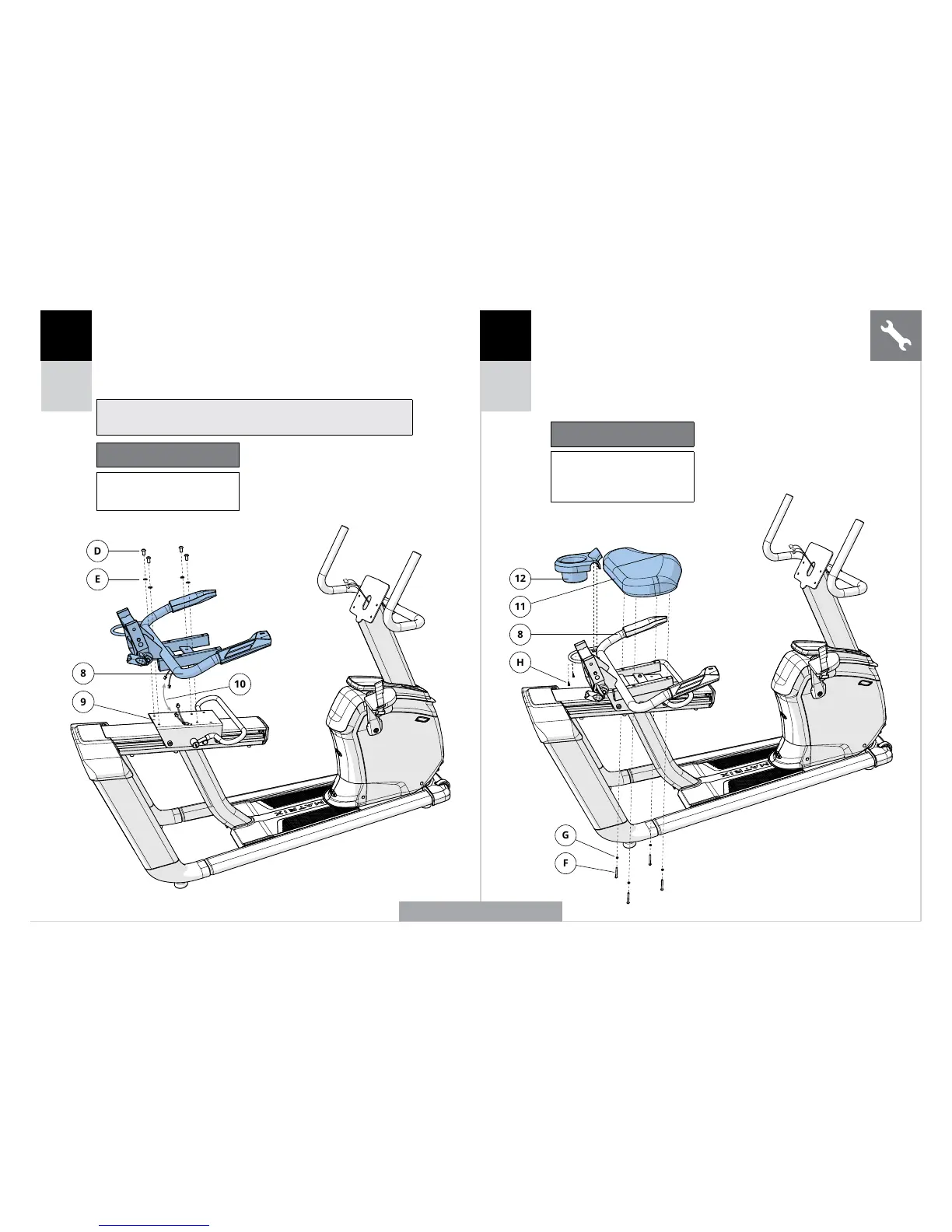
A Abra los COMPONENTES NECESARIOS PARA EL PASO 3.
B Acople el CONJUNTO DE LA ESTRUCTURA DEL ASIENTO (8)
al SOPORTE DESLIZANTE DEL ASIENTO (9) utilizando 4 PERNOS (D)
y 4 ARANDELAS DE PRESIÓN (E). Ajustes del par de apriete:
23,1 Nm / 17 lb-ft.
C Conecte los CABLES (10).
Nota: Tenga cuidado de no estrangular ningún cable al instalar la
estructura del asiento.
Componentes necesarios para
el paso 3
Descripción Cantidad
D Perno 4
E Arandela de presión 4
A Abra los COMPONENTES NECESARIOS PARA EL PASO 4.
B Acople la PIEZA INFERIOR DEL ASIENTO (11) al
CONJUNTO DE LA ESTRUCTURA DEL ASIENTO (8)
utilizando 4 PERNOS (F) y 4 ARANDELAS DE PRESIÓN (G).
C Acople el PORTABIDÓN (12) al CONJUNTO DE LA
ESTRUCTURA DEL ASIENTO (8) con 2 TORNILLOS (H).
Componentes necesarios para
el paso 4
Descripción Cantidad
F Perno 4
G Arandela de presión 4
H Tornillo 2
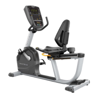
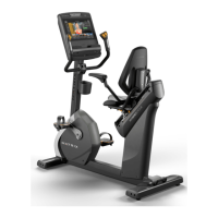
FIGURA DEL MODELO R50
ESPAÑOL
 Loading...