SmartDrive User’s Manual 5
2. SmartDrive Set-Up
Adaptive Clamp Mounting
e SmartDrive adaptive clamp is designed to permanently mount to the axle tube of a wheelchair while presenting a simple
means of attaching/removing the drive unit. Slide the provided hard rubber inserts over the axle receiving tube to accommo-
date smaller tube diameters (see chart below for insert sizing). Use a 5 mm allen wrench to tighten the (2) screws to mount
the clamp to the axle receiving tube. e position and orientation outlined below are critical to the proper function of Smart-
Drive and must be heeded.
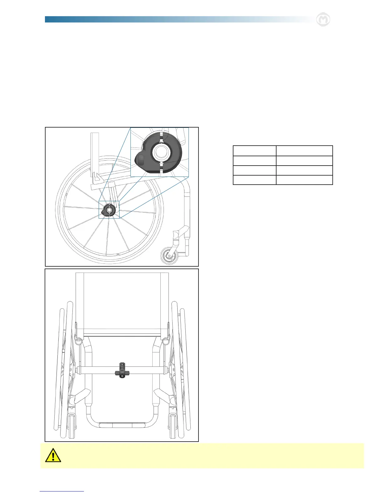
1. Make sure the “MAX” on the front of the clamp is right-
side up. e protrusions coming from the side of the
clamp are to be positioned rearward with the extrusion
ats perpendicular to the ground when the chair [with
the user in it] is resting on a level plane.
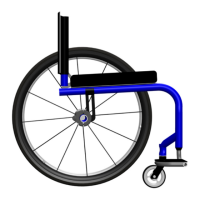
2. e clamp must be positioned midway between the two
rear wheels of the wheelchair on the axle receiving tube.
e two (2) screws should be tightened to 4 ft-lbs, x-
ing it in this position and orientation. Failure to do this
could cause the wheelchair to not drive/ride straight and/
or the clamp to move during use causing the SmartDrive
to not function properly.
Adjustments made to the wheelchair set-up could aect the orientation of the SmartDrive clamp. Adjust the
clamp whenever changes are made to the chair.
CAUTION: e front and back of the clamp will not mate even
when the screws are suciently tight. As shown in the graphic
to the left, there should be a gap between the two parts. Over-
tightening of the screws [more than 4 ft-lbs] could cause the parts
to break during installation.
NOTE: Refer to the separate directions provided for a folding frame wheelchair and skip to step 4 of the “Battery Unit Clipping” sec-
tion.
Dots (or numbers) on the side of the rubber inserts are used
to identify the tube size they t:
No Dots 1.35” or 35 mm
• 1.25” or 32 mm
•• 1.125” or 30 mm
••• 1.0” or 25 mm