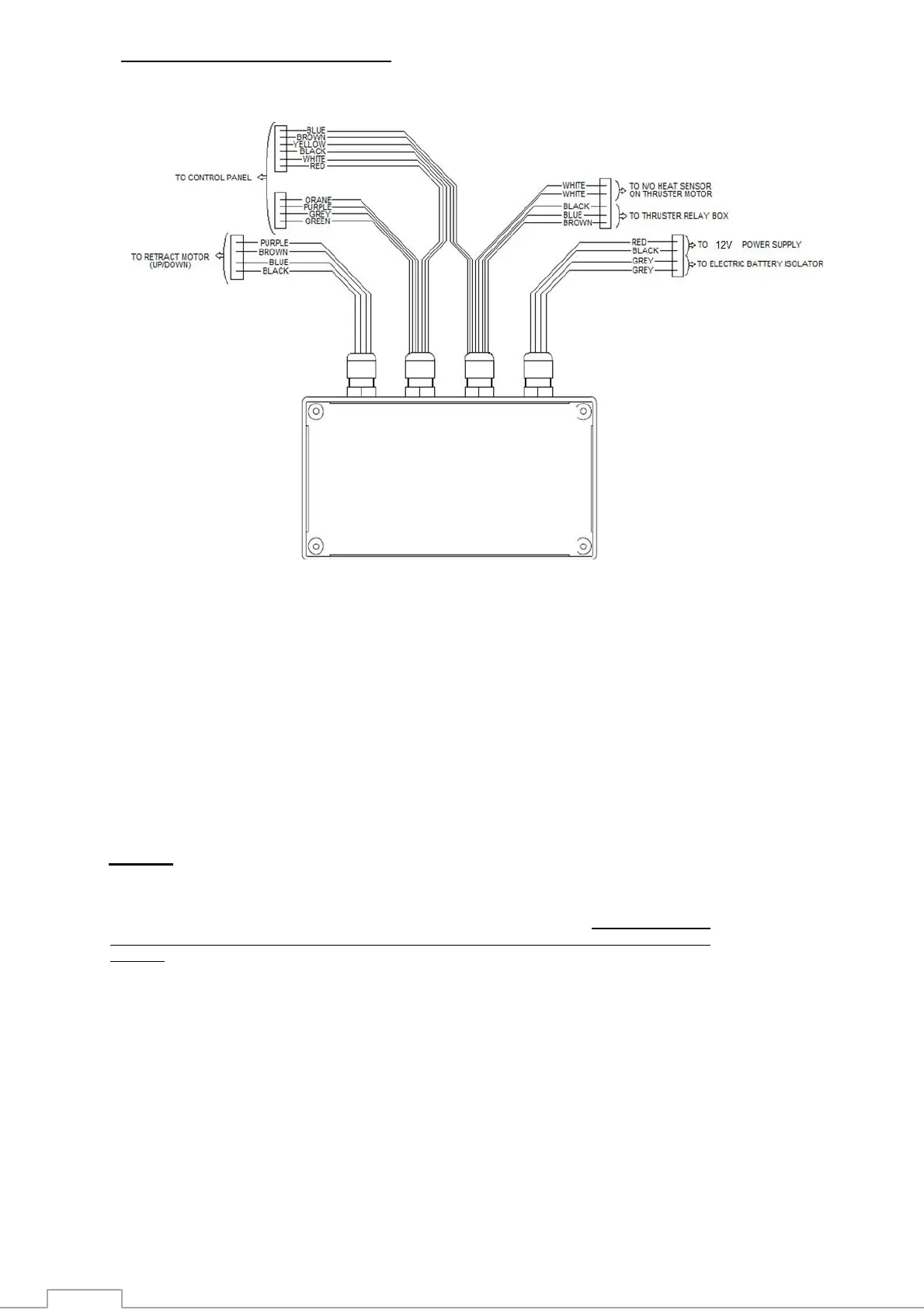
WIRING OF CONTROL BOX after 2017
NOTES:
5. The installer must protect the positive supply cable by means of a fuse (slow blow) as indicated.
The size of these supply wires (min. 2,5mm² with Imax = 15 A) depends on the length of the cable run and
the voltage drop in these cables should not exceed 5% of the nominal battery voltage. For CR70 and CR85
models the command circuit (control panel, control box, up/down servo motor) is always 12V
powered.
6. Install an electric isolator/switch, in the supply of the thruster control box, on the boats main electrical switch board,
marked "Bow Thruster". This breaker or switch should ideally be supplied from a source independent to that used for
the thruster. See "Wiring Diagram" for more detail.
7. All units are supplied with 25 meters of 11-core control cable, although only ten wires are needed to connect control box to
control panel. In order to avoid confusion when doing wiring, it is recommended to connect together the two orange wires
at both control box and control panel ends of the control cable.
8. In comparison with previous versions After 2017 version does not need to configure any toque values from
potentiometers on the electronic controller because the calibration of the leg is done automatically from the
controller.
 Loading...