3. MECHANICAL INSTALLATION
(Please refer to “Build Drawing” at back of this document, see pg 18):
3.1
GENERAL
MAX POWER can supply, either a steel reinforced G.R.P. mounting base or a 5086
aluminium alloy-mounting flange. These bases save considerable shipyard time while
assuring solid and precise installation.
a)
For GRP hulls the mounting base should be laminated into the hull. The base
supplied is only to help give the initial form; its strength will come from additional
lamination (inside and out) added when laminating the hull.
b)
For alloy hulls the mounting flange should be welded onto the base, which has
been fabricated into the hull.
The method and materials used for making the mounting base must be adapted to the
particular hull material (laminated wood, GRP, sandwich, aluminium, or steel). Naval
Architects, Classification Societies or specialised firms should be consulted.
The thruster(s) mechanical stresses are spread over the hull by the mounting base. Its
installation reinforces the hull, if well calculated, but it might be necessary to attach it by
gussets to frames and stringers.
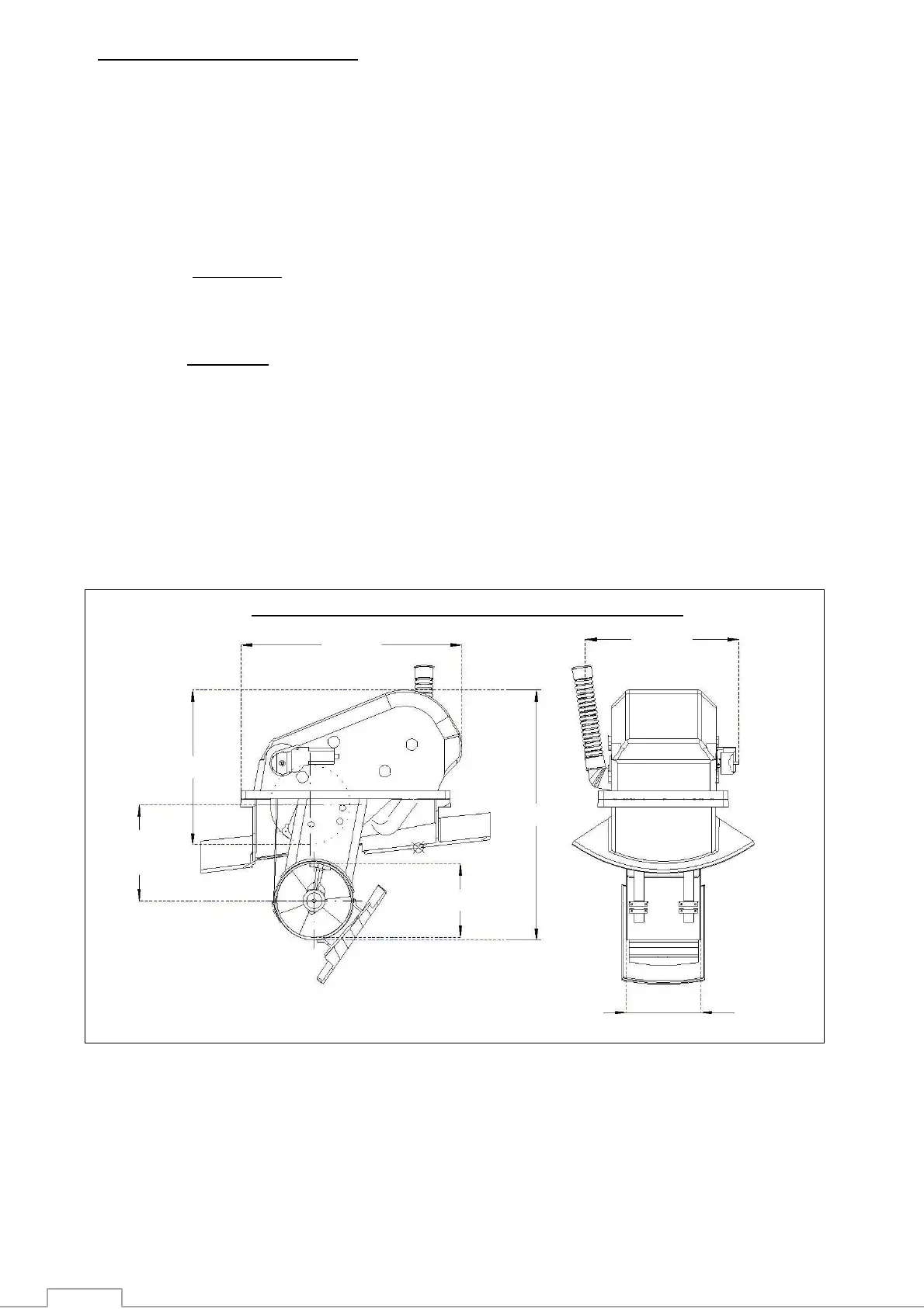
Compact Retract 12/24V Principal Dimensions
When fixing the mounting base, do not forget to take into account the overall dimensions of
the Compact Retract

 Loading...