1. POSITIONING
WARNING: Correct positioning is essential for the correct operation of this unit.
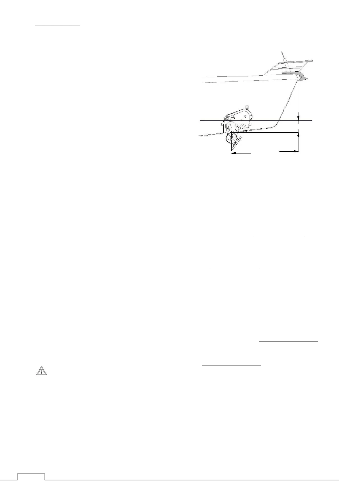
Find the point the farthest forward
(or aft), while keeping in mind the
space available, given the vessel’s
fixtures, space and shape ensuring
you respect the minimum
immersion depth of one full turbine
diameter (185 mm).
Always check and make sure that there is enough room to allow for the complete
removal of the thruster unit and enough room for the connection of the electric cables.
To install a Compact Retract in the stern, make sure that the turbine flow is clear
of all obstacles, or select the best possible compromise.
2. DETERMINE THE LOCATION OF THE AUXILIARY EQUIPMENT
A power fuse, of the correct size(see section 4.3), must be installed in the positive supply
cable, as close as possible to the thruster’s battery bank and it must be easily accessible and
clearly marked.
A manual battery isolator, of the correct size, should be installed in the positive supply cable, as
close as possible to the thruster’s battery bank and must be easily accessible and clearly marked
An electrical battery isolator, as supplied by Max Power, should be installed in the positive
supply cable, as close as possible to the thruster’s battery bank, in order to benefit from all
automatic safety features of the electronic control system.
The thruster electronic control box should be installed in proximity of the thruster unit in a
completely dry and ventilated area.
The thruster relay box should be installed in proximity of the thruster unit, above the waterline
in a completely dry and ventilated area.
The thruster motor terminal busbar should be installed above the waterline.
Care should be taken to securely fix the opening of the black rubber hose, containing
power cables, above the vessel’s waterline.
The control panel(s) should be installed as desired at the helm station(s) in a protected and
waterproof position.
As far forward
as possible
 Loading...