Via Mediterraneo, 6 - 42022 - Boretto - Reggio Emilia - Italy
Tel. +39 - 0522-96 30 08 - Fax +39 - 0522-96 30 39
info@maxiliftcrane.com
- 3 -
Finally, the operating system is the hydraulic or electro-hydraulic system transmitting the movement to the actuators
(cylinders). It is consisting of a pump (electric or manual) and control system (button strip or hydraulic valve bank).
In this type of crane the slewing support and column assembly make up the slewing system, which can be of three
types:
¾ thrust rotation;
¾ crank rotation (operating a worm screw – worm wheel gear);
¾ hydraulic (hydraulic motor operating a worm screw – worm wheel gear).
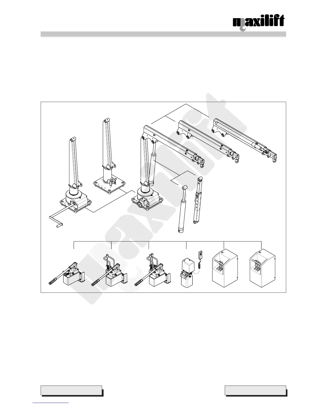
3.3 Crane composition
A1 Thrust slewing system (6.6.1)
A2 Crank slewing system (6.6.2)
A3 Hydraulic slewing system (6.6.3)
B1 Boom lifting system by mechanical strut (6.6.4)
B2 Boom lifting system by hydraulic cylinder (6.6.5)
C1 Two manual extensions boom system (6.6.6)
C2 Boom system with 1
st
hydraulic and 2
nd
manual extensions (6.6.7)
D1 Hydraulic operating system with hand pump for lifting cylinder (6.6.8)
D2 Hydraulic operating system with hand pump for lifting and extension cylinders (6.6.9)
D3 Hydraulic operating system with hand pump for extension cylinder (6.6.10)
D4 Electro-hydraulic operating system by power unit with single function for lifting cylinder (6.6.11)
D5 Electro-hydraulic operating system by power unit with two functions for lifting and extension cylinders (6.6.12) or
for slewing and lifting cylinder (6.6.13)
D6 Electro-hydraulic operating system by power unit with three functions for slewing, lifting and extension cylinders
(6.6.14)
Pict. 3
A2
Lifting
Boom system
Slewing system
Operating system
A1
C2
C1
B1
B2
D1 D2 D3 D4 D5 D6
A3



 To Next Page