Page 1 System Components
Page 2 & 3 Introduction and Dimensions
Page 4 Specications
Installation of Components
Typical Gas Trains
Page 5 Field Service Checklist
Page 6 Preliminary Circuit Analysis
Page 7 Wiring Diagrams
Sensitivity Adjustment
Low Fire Start Time Adjustment
Page 8 Temperature Calibration
Valve Adjustments
1
Series 44 Installation Instructions
© 2008 Maxitrol Company, All Rights Reserved
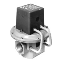
SYSTEM COMPONENTS
A1044U
A1044U (replaces all A1044L1, suitable re-
placement for A1044 [C,D,E,H]) (includes 0,
A1044UF (replacement for A1044FL1)
A1044UG (replacement for A1044G[L1])
NOTE:-
ture Sensor must have same temperature
Sensors compatible with A1044U:
Sensors compatible with A1044UF:
Sensors compatible with A1044UG:
speed blower or dual fuel operation)
NOTE: M (Modulator) valve requires an
-
tor) valve requires no upstream pressure
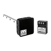
Selectrastat (Senses and Selects)
or optional pair to replace
Selectrastat
Space Temperature Selector
Space Temperature Sensor
NOTE:
-
perature Sensor must have
same temperature range to be