Do you have a question about the maxon motor ESCON 50/5 and is the answer not in the manual?
Information about the document's purpose, audience, and notation used within the manual.
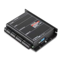
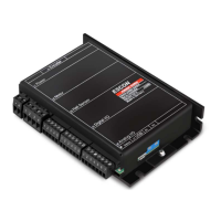
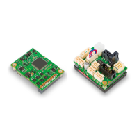
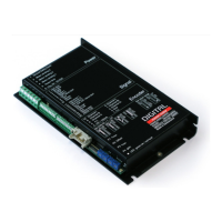
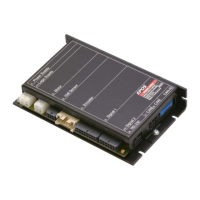
Details the ESCON 50/5 servo controller, its features, operating modes, and configuration methods.
Essential safety warnings, potential hazards, and mandatory precautions for safe operation and handling.
Comprehensive list of technical specifications, electrical ratings, dimensions, and operating conditions.
Lists the compliance standards and certifications relevant to the ESCON 50/5 servo controller.
Key rules and guidelines applicable to the setup and installation of the ESCON 50/5 controller.
Guidance on selecting the correct power supply, including requirements and calculation methods.
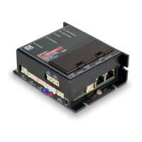
Overview of all connectors and interfaces on the ESCON 50/5, detailing their purpose and connections.
Pin assignment and specifications for the J1 power input connector.
Pin assignment and specifications for the J2 motor output connector for DC or EC motors.
Pin assignment and specifications for the J3 Hall sensor input connector.
Pin assignment and specifications for the J4 encoder input connector.
Pin assignment and specifications for the J5 digital inputs and outputs.
Pin assignment and specifications for the J6 analog inputs and outputs.
Pin assignment and specifications for the J7 USB connector for PC communication.
Details the location and adjustment range of the onboard potentiometers for configuration.
Explanation of the status LEDs, their colors, and conditions they indicate.
Wiring diagrams and connection examples for integrating DC motors with the ESCON 50/5.
Wiring diagrams and connection examples for integrating EC motors with the ESCON 50/5.
List of available spare parts, including order numbers and descriptions.
| Continuous Current | 5 A |
|---|---|
| Peak Current | 10 A |
| Max. Peak Output Current | 10 A |
| Communication Interface | RS232 |
| Protection Features | Overcurrent, Overtemperature |