TABLE OF CONTENTS
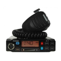
MAXON SM-2000 MOBILE
TABLE OF CONTENTS
Page-i-
December 98
Table Of Contents....................................................i
Specifications........................................................1
Transceiver Nominal Performance ......................................1
General ...........................................................1
Transmitter ........................................................2
Tx Tone Modulation Characteristics .....................................4
Sub Audible Tones - DCS .............................................4
Receiver...........................................................4
Rx Tone Demodulation Characteristics...................................5
Accessories ........................................................5
Reliability Analysis ..................................................5
Programmer ........................................................5
Introduction ........................................................6
Unpacking Information ...............................................7
General Description ..................................................8
Description Of Controls ...............................................9
Theory Of Operation .................................................11
RF Section (SM-2150/VHF) ...........................................13
RF Section (SM-2450/UHF) ...........................................17
PLL ..............................................................20
Test Setup ..........................................................21
SM-2150/VHF Alignment Procedure ....................................22
Alignment Points Diagram (SM-2150/VHF) ..............................26
SM-2450/UHF Alignment Procedure ....................................27
Alignment Points Diagram (SM-2450/UHF) ..............................31
Component Replacement..............................................32
Surface Mount Components ...........................................32
Surface Mount Removal ..............................................32
Surface Mount Component Replacement .................................33
Surface Mounted Integrated Circuit Replacement ..........................33
Parts List Common to SM-2000 ........................................34
Electrical Parts List Main Board Digital Section (SM-2000) .................35
Electrical Parts List Band Chart (SM-2150/VHF) .........................37
Electrical Parts List Main Board (SM-2150/VHF) .........................38
Electrical Parts List Band Chart (SM-2450/UHF) .........................42
Electrical Parts List Main Board (SM-2450/UHF) .........................44
Component Pinout (SM-2000)..........................................48
Voltage Charts (SM-2150/VHF) ........................................51
Voltage Charts (SM-2450/UHF) ........................................54
Trouble Shooting Chart (SM-2000) .....................................57
 Loading...