Page 11 of 13 M-KIT112/113/114 Assembly Instrucons 181-03005
These instrucons must be followed exactly. Failure to follow these instrucons could damage the product or result in injury to persons
using or assembling the product. Maxon Furniture Inc. shall not be liable for any costs, loss, damage, expenses or injuries resulng from
failure to properly assemble the product in accordance with these instrucons.
Maxon Furniture Inc. Customer Service: 1-800-876-4274
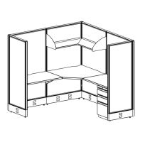
Adding the Worksurfaces
1. Unpack the UCS2436TM Corner Worksurface
and unscrew the Canlever Brackets from the
worksurface.
2. Posion the Le-hand Canlever Bracket into
le hand panel slots in the Back Le Panel at
about 28” from the oor (Figure 18).
3. With the Canlever lted up about 45 degrees,
slide the top tooth into the panel slot, then
rotate the canlever down to engage the
other teeth (Figure 19).
4. Repeat Steps 2 - 3 to install the Right-hand
Canlever Bracket on the right hand slots of
the Back Right Panel.
5. Add one RH Corner Bracket in the back corner
at the same height as the Canlever Brackets
(Figure 20). The RH Corner Bracket is shown,
but you can use either the LH or RH Corner
Bracket.
6. Place the UCS2436TM Corner Worksurface
into posion on the Canlevers and Corner
Bracket.
7. Secure the UCS2436TM Corner Worksurface
with three #10 x 3/4” Panhead Screws in each
Canlever and one #10 x 3/4” Panhead Screw
in the RH Corner Bracket (Figure 21).
Figure 20
Figure 19
Figure 21
Figure 18
RH Corner
Bracket
#10 x 3/4" Panhead Screw
(3 in ea. Cantilever,
1 in RH Corner Bracket)
28"
Left-hand
Cantilever
Right-hand
Cantilever
RH Corner
Bracket
Back Left
Panel
Back Right
Panel
Left-hand
Cantilever
 Loading...