Page 12 of 13 M-KIT112/113/114 Assembly Instrucons 181-03005
These instrucons must be followed exactly. Failure to follow these instrucons could damage the product or result in injury to persons
using or assembling the product. Maxon Furniture Inc. shall not be liable for any costs, loss, damage, expenses or injuries resulng from
failure to properly assemble the product in accordance with these instrucons.
Maxon Furniture Inc. Customer Service: 1-800-876-4274
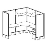
8. Unpack one UWR2436TM Rectangular
Worksurface and unscrew the two (2)
Canlever Brackets from the worksurface.
9. Install the Le-hand and Right-hand Canlever
Brackets onto the PL6636 Panel [to the le
of the UCS2436TM Corner Worksurface] at
the same height as the UCS2436TM Corner
Worksurface (Figure 22).
10. Install one LH Corner Bracket at the same
height as the Canlevers into the le PL6624
Panel on the inside of the staon.
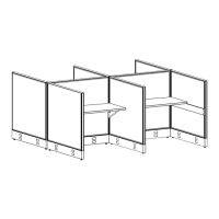
11. Posion one UWR2436TM Rectangular
Worksurface onto the Canlevers and Corner
Bracket and secure with three #10 x 3/4”
Panhead Screws in each Canlever and one
#10 x 3/4” Panhead Screw in the Corner
Bracket (Figure 23).
12. Posion the Aaching Bracket near the front
at the adjoining edges of the Corner and the
Rectangular Worksurfaces. Secure with four
(4) #10 x 3/4” Panhead Screws in the pre-
marked worksurface holes (Figure 23).
13. Repeat steps 8 - 12 with the second
UWR2436TM Rectangular Worksurface using
the RH Corner Bracket in the right side of the
PL6624 Panel.
Figure 23
Figure 22
#10 x 3/4" Panhead screws
(3 in each Cantilever,
1 in the LH Corner Bracket,
4 in the Attaching Bracket)
Attaching Bracket
Right-hand
Cantilever
Bracket
LH Corner Bracket
Left-hand
Cantilever Bracket
 Loading...