Page 10 of 11 M-KIT118/119/120 Assembly Instrucons 181-03007
These instrucons must be followed exactly. Failure to follow these instrucons could damage the product or result in injury to persons
using or assembling the product. Maxon Furniture Inc. shall not be liable for any costs, loss, damage, expenses or injuries resulng from
failure to properly assemble the product in accordance with these instrucons.
Maxon Furniture Inc. Customer Service: 1-800-876-4274
Unpack the four UWR2448TM Rectangular 1.
Worksurfaces.
TIP! Only two worksurfaces will
have a Le-hand Canlever Bracket
and a Right-hand Canlever Bracket
aached.
Unscrew the Canlever Brackets from the 2.
worksurfaces.
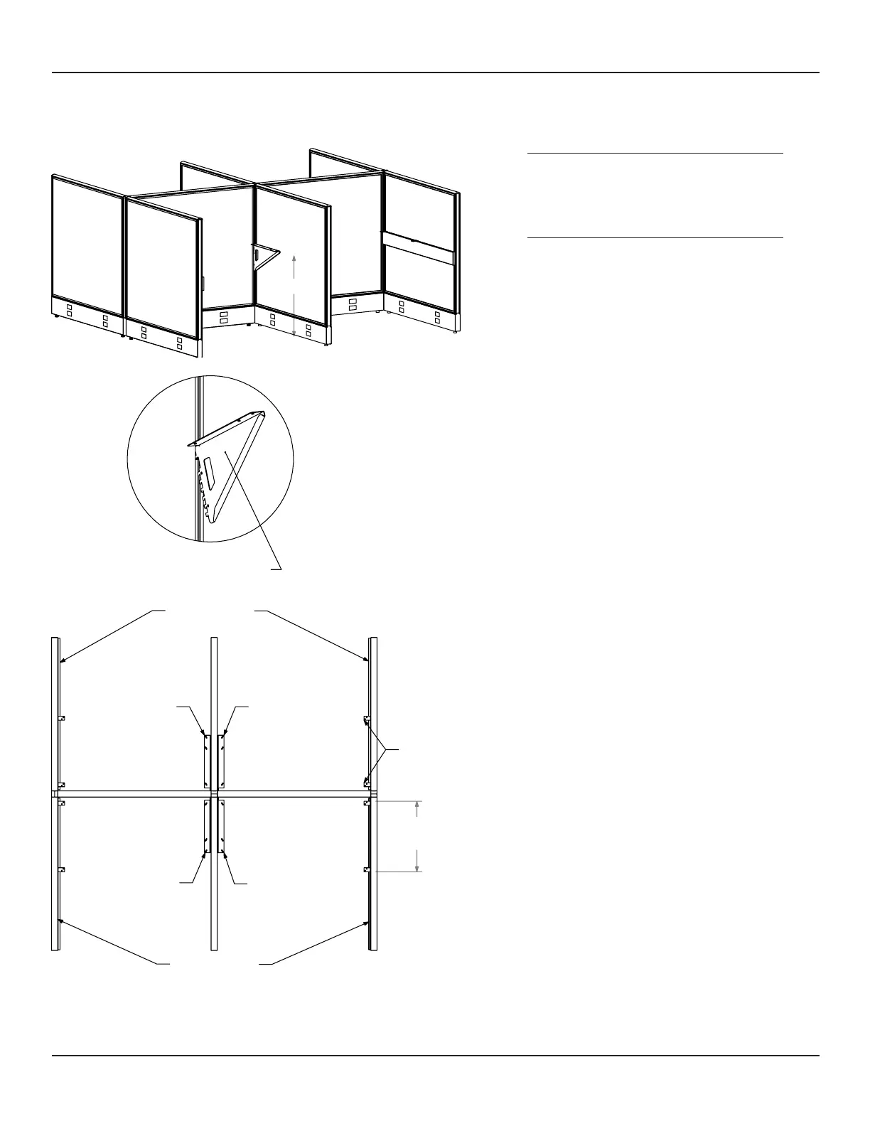
Posion a Right Hand Canlever Bracket into 3.
the Panel slots at the same height as the
Spanner Rails (Figure 11).
With the Canlever lted upward about 45°, 4.
slide the top tooth into the PL4848 Panel slot,
then rotate the Canlever down to engage the
other teeth (Figure 12).
Repeat steps 3 - 4 to install the remaining 5.
Canlever Brackets into the PL4848 Panels
(Figure 13).
Place a UWR2448TM Worksurface into 6.
posion on a Canlever Bracket and LLSR48
Spanner Rail.
Conrm that this is the desired worksurface 7.
height and reposion the Canlever Brackets
and LLSR48 Spanner Rails, if necessary.
Installing the Worksurfaces
Figure 13
Figure 12
Figure 11
28"
Right Hand
Cantilver Bracket
22"
Approx.
Top View
Right Hand
Cantilever
Right Hand
Cantilever
Left Hand
Cantilever
Left Hand
Cantilever
Spanner Rail
Spanner Rail
Spanner
Clips
 Loading...