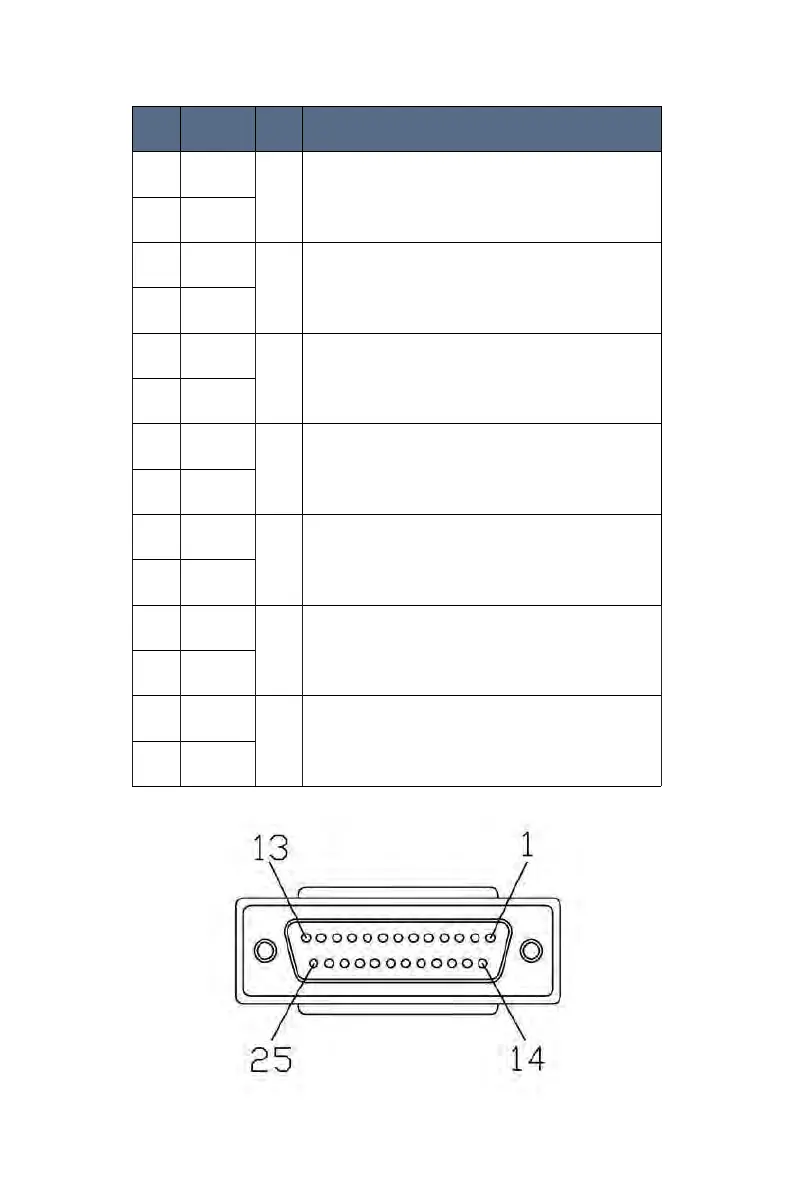
PIN # Signal Name Type Functionality
16 Enable+
IN
Laser Enable
Laser Enable ON/OFF; when the voltage is high(24V), Laser Enable is ON;
when voltage is low(0V), Laser Laser Enable is OFF.
3 Enable-
18 EX-CTRL+
IN
External Start
External control Laser Emission ON/OFF; when the voltage is high(24V),
Laser Emission is ON; when voltage is low(0V), Laser Emission is OFF.
When Enable and EX-CTRL are ON, Laser is ON.
5 EX-CTRL-
14 Error 1
OUT
Alarm Output
Connect to external LED Bar to indicate the Alarm status; the two pins are
Relay output pins; When LASER works normally, the two pins open, when
LASER has error, the two pins close.
1 Error 2
7 EXLOCK1-
Contact
Closure
Interlock1 Input
External Safety interlock; Potential free contacts.
Laser cannot be started without the two pins connected together.
DO NOT connect an external voltage.
20 EXLOCK1+
9 EXLOCK2-
Contact
Closure
Interlock2 Input(Only for MA1-35)
External Safety interlock; Potential free contacts.
Laser cannot be started without the two pins connected together.
DO NOT connect an external voltage.
22 EXLOCK2+
19 EMG1 +
IN
Emergency Stop Input1
When the voltage is high(24V), the Emergency Stop is triggered (Valid);
When the voltage is low(0V), the Emergency Stop is NOT triggered(invalid)
6 EMG1 -
21 EMG2 +
IN
Emergency Stop Input2(Only for MA1-35)
When the voltage is high(24V), the Emergency Stop is triggered (Valid);
When the voltage is low(0V), the Emergency Stop is NOT triggered(invalid)
8 EMG2 -
EX-CTRL Description (Security interface)(DB25)