K
kendra41Aug 8, 2025
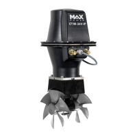
Why does my MaxPower CT80 thruster lack power?
- DDeanna JenningsAug 8, 2025
To address a lack of power in your MaxPower Boat thruster, verify the propellers are properly fitted. Also, check the battery size, ensure the batteries are sufficiently charged, and confirm all connections are correctly tightened. It's also important to inspect the power cable sections, referring to page 6 for recommended cable sizes.