6
CAUTION: Please strictly follow installation procedure when you want to connect PV or DC
terminals. Don’t touch the DC terminals and the PV terminals by hand. Failure to follow these
instructions can result in serious electrical shock.
Connect to the Load
Remove insulation sleeve 10mm for three conductors. And shorten phase L and neutral conductor N 3 mm.
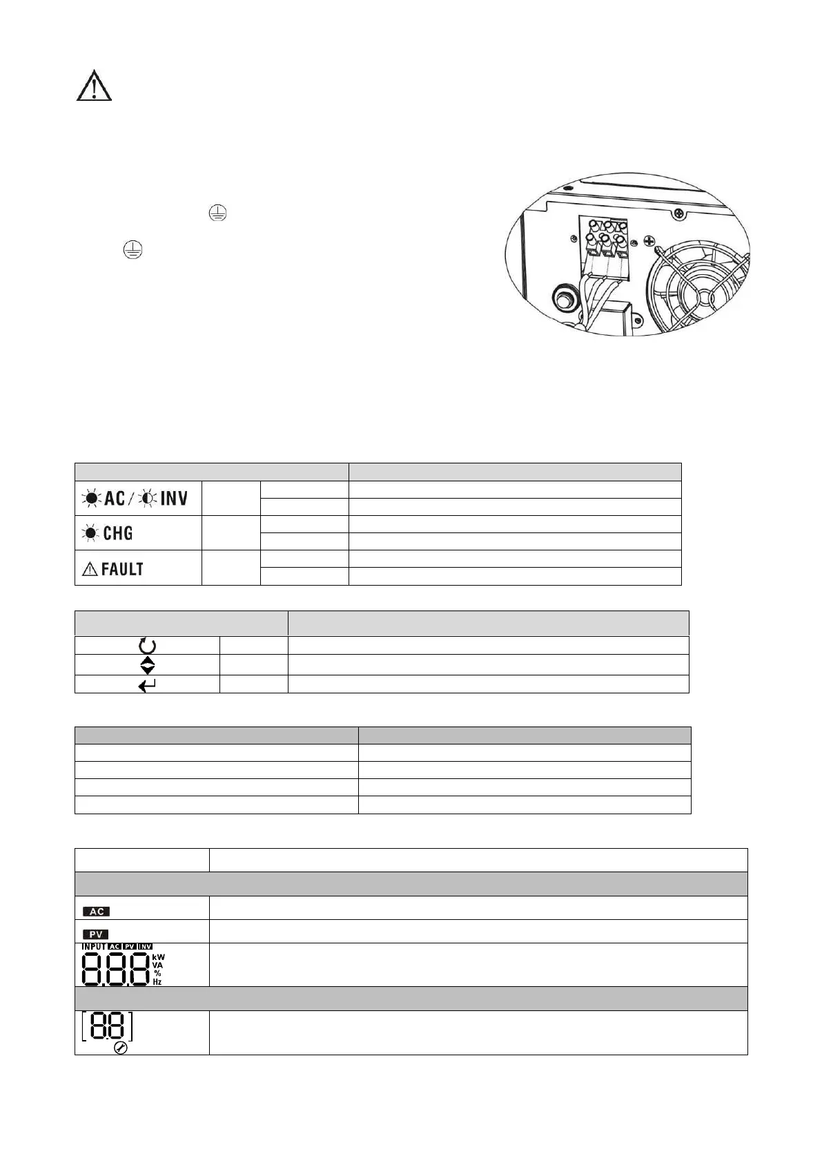
Insert AC output wires according to polarities indicated on terminal
block and tighten the terminal screws. Be sure to connect PE
protective conductor ( ) first.
→Ground (yellow-green)
L→LINE (brown or black)
N→Neutral (blue)
5. Operation
Power On/Off
Once the inverter has been properly installed, press the power switch to turn on the unit. The unit will work
automatically in line mode or inverter mode according to input utility power's status. When press the power
switch again, the unit will be turned off.
LED Indicators, Function Keys & Audible Alarms
There are three indicators in the front panel of the unit.
Output is available in bypass mode
Output is powered by battery in inverter mode
Battery is charging by SCC
Battery is not charging by SCC while SCC power on
battery low or overload warning
Function Keys
To confirm the selection in setting mode or enter setting mode
Audible Alarms
Inverter Mode (Low-battery Voltage)
LCD Display
Indicates input voltage, input frequency, PV voltage, charging current, main board
firmware version and SCC firmware version
Configuration Program and Fault Information
Indicates the setting programs.