ENGLISH 10 WWW.MAXTEC.COM • (800) 748-5355
3.1 Blender Safety Check
NOTE: Before proceeding, ensure that the high alarm set point control is OFF [display reads
(--)], and that the low alarm set point control is below 20%.
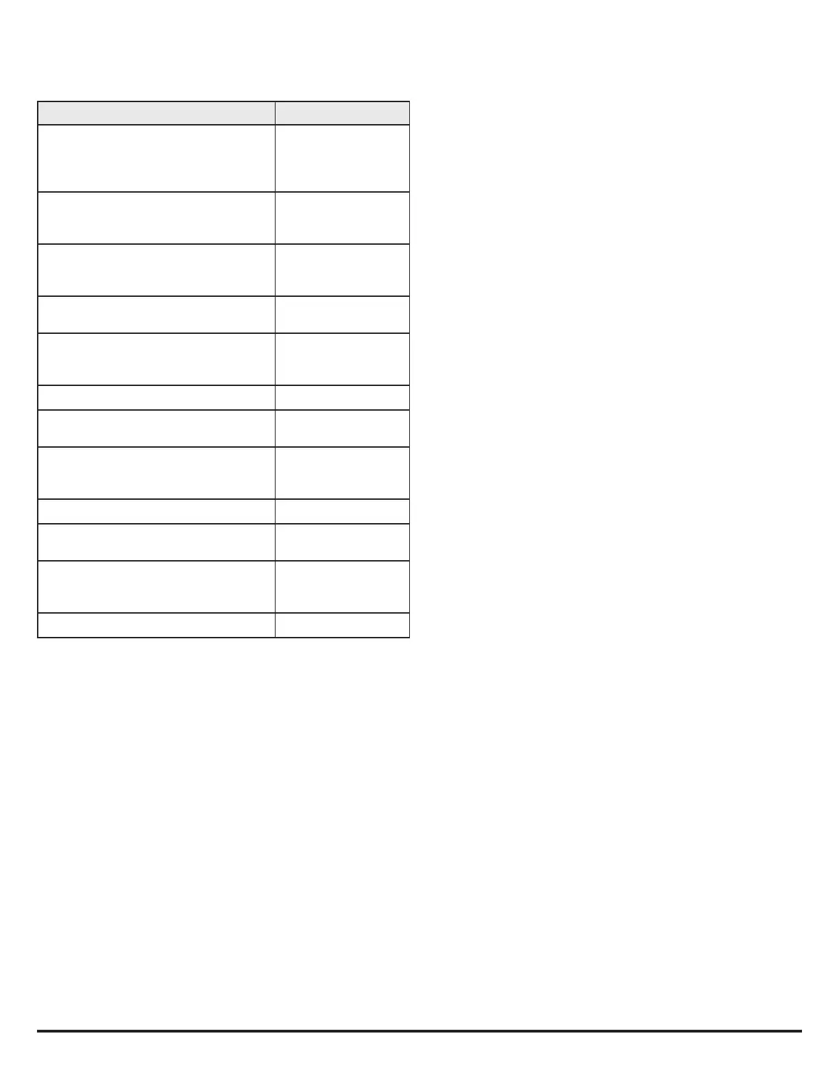
PROCEDURE BLENDER RESPONSE
1. Connect the blender to 50 ±5 PSIG air/oxygen gas
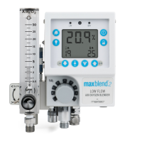
sources. Adjust the blender control knob to 60%.
Turn the bleed toggle switch on (up position) and
adjust the flowmeter to a minimum of 2 LPM.
No response. Monitor
display reads 60% ±3%.
2. Disconnect the 50 PSIG AIR source from the MaxBlend 2.
NOTE: The blender must be flowing
gas for the alarm to activate.
Audible alarm sounds. Monitor
display reads 100% ±3%.
3. Reconnect 50 PSIG AIR source to the MaxBlend 2.
Audible alarm stops.
Verify the monitor display
reads 60% ±3%.
4. Disconnect 50 PSIG OXYGEN source
from the MaxBlend 2.
Audible alarm sounds. Monitor
display reads 20.9% ±3%.
5. Reconnect 50 PSIG OXYGEN to the MaxBlend 2.
Audible alarm stops.
Verify the monitor display
reads 60% ±3%.
6. Adjust both air and oxygen inlet regulators to 0 PSIG. No response.
7. Remove air inlet hose at regulator and
insert end into beaker of water.
No response.
8. Slowly raise pressure of oxygen regulator
to 50 PSIG and back to 0 PSIG while
observing air hose end in beaker.
No bubbles should
be observed. Audible
alarm sounds.
9. Dry and reattach air inlet hose to regulator. No response.
10. Remove oxygen inlet hose at regulator,
and insert end into beaker of water.
No response.
11. Slowly raise pressure of air regulator to
50 PSIG and back to 0 PSIG while observing
oxygen hose end in beaker.
No bubbles should
be observed. Audible
alarm sounds.
12. Dry and reattach oxygen inlet hose to regulator. No response.
4.0 TROUBLESHOOTING
PROBLEM: Oxygen concentration discrepancy between oxygen concentration selection knob
and actual reading on display, greater than 3%.
POTENTIAL CAUSES AND SOLUTIONS:
•
Bleed is turned off. Turn bleed toggle switch on. Refer to section 2.9, Flowmeter
Operation.
•
Monitor out of calibration. Calibrate. Refer to section 2.8, Calibration Procedure.
•
Sensor exhausted. Replace sensor. Refer to section 6.2.
•
Gas supply contaminated. Contact Maxtec for repair of the MaxBlend 2.
•
Blender out of calibration. Contact Maxtec for repair.
PROBLEM: Pressure differential alarm sounding.
POTENTIAL CAUSES AND SOLUTIONS:
•
Inlet pressure differences of 20 PSI or more. Correct pressure difference.
•
Pressure alarm not calibrated properly. Contact Maxtec for repair.
•
MaxBlend 2 blender operation out of calibration. Contact Maxtec for repair.
PROBLEM: Inlet pressure has supply loss, no audible pressure differential alarm.
POTENTIAL CAUSES AND SOLUTIONS:
•
Reed alarm cap damaged or defective. Contact Maxtec for repair.
PROBLEM: Selected oxygen concentration accurate only when gas pressures are equal.
POTENTIAL CAUSES AND SOLUTIONS:
•
MaxBlend 2 balance module not functioning properly. Contact Maxtec for repair.
PROBLEM: Blank display.
POTENTIAL CAUSES AND SOLUTIONS:
•
Batteries not installed. Install batteries. Refer to section 2.1.1, Battery Installation.
•
Battery completely dead. Replace batteries. Refer to section 2.1.1, Battery Installation.
•
Monitor defective. Contact Maxtec for repair.
PROBLEM: Partial or distorted display.
POTENTIAL CAUSES AND SOLUTIONS:
•
Monitor damaged. Contact Maxtec for repair.
PROBLEM: Sensor will not calibrate.
POTENTIAL CAUSES AND SOLUTIONS:
•
Sensor cell exhausted. Replace sensor. Refer to section 6, Replacing O2 sensor.
•
Sensor cable defective. Return to Maxtec.
•
Monitor defective. Contact Maxtec for repair.
PROBLEM: Sensor will calibrate, but takes too long or does not return to 21% ±2% oxygen in air
(2 to 5 minutes) when performing calibration.
POTENTIAL CAUSES AND SOLUTIONS:
•
Disposable oxygen sensor damaged or defective. Replace sensor. Refer to section 6.2,
Replacing O2 sensor.
PROBLEM: Sensor will calibrate, but reading at any constant level drifts more than ±3% over
a 24 hour period.
POTENTIAL CAUSES AND SOLUTIONS:
•
Barometric pressure change since last calibration. Recalibrate. Refer to section 2.8,
Calibration Procedures.
•
Room or gas temperature went below 59°F (15°C) or above 104°F (40°C). Correct
temperature and recalibrate.
PROBLEM: Low battery icon.
POTENTIAL CAUSES AND SOLUTIONS:
•
If, at any time, the low battery icon is displayed on the LCD readout, the batteries
should be replaced as quickly as possible.
PROBLEM: E01: Sensor voltage is too low to perform a valid calibration.
POTENTIAL CAUSES AND SOLUTIONS:
•
Manually attempt a new calibration. Refer to section 2.8, Calibration Procedures.
•
If unit repeats this error more than three times, contact Maxtec’s Customer Service
Department for possible sensor replacement.
PROBLEM: E02: No sensor attached.
POTENTIAL CAUSES AND SOLUTIONS:
•
Disconnect the sensor and reconnect, making sure the male plug is fully inserted into
the receptacle. The analyzer should now perform a new calibration with the error
cleared.
•
If the error still persists, remove the batteries, wait 30 seconds, then reinstall, to
perform a factory reset and diagnostic on the analyzer. The analyzer should again
perform a new calibration with the error cleared.
•
Contact Maxtec Customer Service Department if the error code cannot be cleared.
PROBLEM: E03: No valid calibration data available.
POTENTIAL CAUSES AND SOLUTIONS:
•
Make sure unit has reached thermal equilibrium and perform a calibration routine.
Refer to section 2.8, Calibration Procedures.
PROBLEM: E04: Battery below minimum operating voltage.
POTENTIAL CAUSES AND SOLUTIONS: