WWW.MAXTEC.COM • (800) 748-5355 7 ENGLISH
j
OXYGEN LOW ALARM LIMIT — Low oxygen alarm setpoint. Audible and visual alarms will
trigger when this limit is exceeded.
k
LOW ALARM INDICATOR — The low alarm setting is displayed at all times just below
the “LOW” icon on the LCD readout. The indicated value represents the oxygen percent-
age at which the low alarm will be activated.
l
<18% ALARM INDICATOR — The <18% alarm indicator is located above the Low Alarm
Indicator digits. When the low alarm setting is set below <18%, the indicator will flash
each second to alert the operator of this special condition. See section 2.3.1 for setting
this low alarm condition.
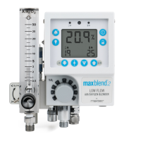
1.6 Back View
v
BATTERY COMPARTMENT — The MaxBlend 2 is powered by four “AA” alkaline batteries.
b
SENSOR CABLE — The cable connects the MaxBlend 2 to the MAX-550E Sensor.
n
SENSOR WITH DIVERTER — The sensor with flow diverter is designed to fit into a port
behind the flowmeter.
m
O2 SENSOR PORT — A sampling port for the oxygen sensor. It allows mixed gas from the
blender to flow over the sensor membrane.
,
PRESSURE DIFFERENTIAL REED ALARM — An audible alarm which, when activated,
indicates that an unacceptable pressure differential exists between the two gas source
pressures.
.
AUXILIARY MIXED GAS OUTLET — The outlet can be used as power take off.
/
AUXILIARY MIXED GAS OUTLET — The outlet can be used to add additional flowmeters.
Q
MOUNT ADAPTER — An adapter which allows the MaxBlend 2 to be mounted onto a
bracket for attaching to a rail or ventilator system.
W
EXTERNAL POWER SUPPLY PORT — The port provides connection for the external power
adapter. See section 2.7 for more information on the power supply.
1.7 Requirements for Operating the Blender
All operator-detachable inlet pressure hoses supplied with the gas mixer comply with ASTM/
ISO 5359.
PRESSURIZED OXYGEN: The compressed oxygen source must provide clean, dry, medical-
grade oxygen at the pressure specified in Section 8.0.
PRESSURIZED AIR: The compressed air source must provide clean, dry, medical-grade air at
the pressure specified in Section 8.0.
2.0 OPERATING PROCEDURES
2.1 Setup and Installation
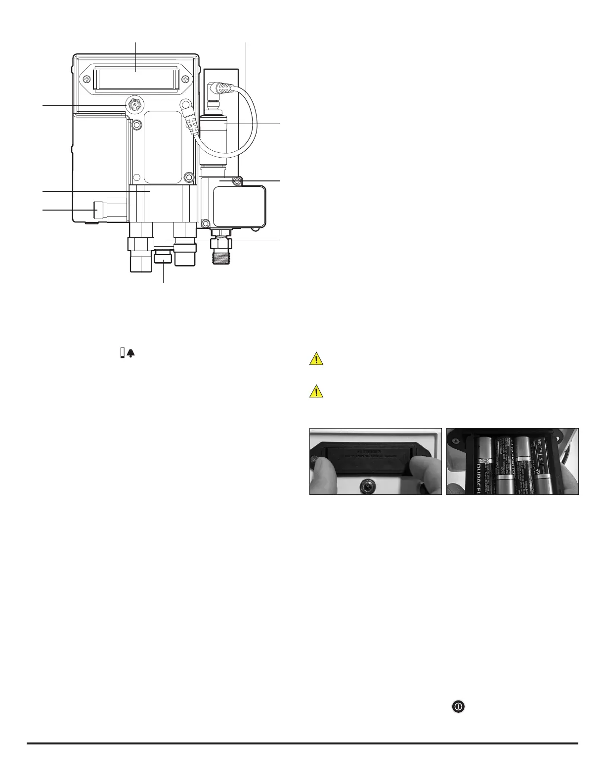
2.1.1 Battery Installation
All MaxBlend 2 units are powered by four “AA” alkaline batteries (4 x 1.5 Volts) and are shipped
without the batteries installed. Only name-brand batteries should be used. Batteries should
be replaced by trained service personnel.
To install the batteries:
Open the battery drawer by squeezing inward on both tabs as shown in the figure below. If
you have difficulty squeezing the tabs in with your fingers, use two flat screwdrivers or two
coins. Remove the battery drawer completely from the MaxBlend 2. Install four new, “AA”
alkaline batteries into the unit, observing the orientation shown on the plastic inside the
drawer. Slide the drawer back in with the batteries facing upward. Press in on the drawer until
both tabs latch into place.
When batteries are replaced, the unit will start up and perform an automatic calibration.
Ensure calibration is performed as directed in Section 2.8.
WARNING: Battery replacement by inadequately trained personnel could result in a
safety hazard.
WARNING: Electrical shock or damage to the equipment may occur if an inappropri-
ate external power supply is used. Maxtec recommends using only the Maxtec MaxBlend 2
External Power Supply—R230P10.
2.1.2 MaxBlend 2 Setup
1. Connect the pressurized air source to the Air Inlet Connector.
2. Connect the pressurized oxygen source to the O2 Inlet Fitting.
3. Flush gas at the highest possible flow rate through the blender for at least one minute
to eliminate any particulate that may have been introduced into the system during
handling and installation.
2.1.3 Sensor Installation
1. Attach the flow diverter onto the oxygen sensor.
2. Place the sensor into the sensor port located behind the flowmeter.
3. Attach the sensor cable directly to the sensor and the sensor jack on the back of the
monitor enclosure. Ensure the cable is fully inserted into both connections.
4. Calibrate the sensor prior to use according to the calibration procedures in section 2.8
2.2 Monitoring
Before use on a patient, the oxygen concentration of the delivered gas should be checked at
the setting intended for use.
1. To begin monitoring, press the ON/OFF key located on the front panel. Monitoring
will begin immediately.
v b
.
n
m
,
/
Q
W