866.4.Maxtec www.maxtec.com 25
Floors should be wood, concrete or ceramic tile.
If floors are covered with synthetic material, the
relative humidity should be kept at levels to
reduce electrostatic charge to suitable levels.
Mains power quality should be that of a typical
commercial or hospital environment.
Mains power quality should be that of a typical
commercial or hospital environment.
Equipment which emits high levels of power
line magnetic fields (in excess of 3A/m) should
be kept at a distance to reduce the likelihood
of interference.
Mains power should be that of a typical commercial
or hospital environment. If user requires continued
operation during power mains interruptions insure
that batteries are installed and charged. Insure that
battery life exceeds longest anticipated power
outages or provide and additional uninterruptible
power source.
>95%, 0.5 per.
60%, 5 per.
30%, 25 per.
>95%, 5 sec.
3 A/m
± 2 kV
± 1 kV
± 2 kV
± 1 kV
± 6 kV
± 8 kV
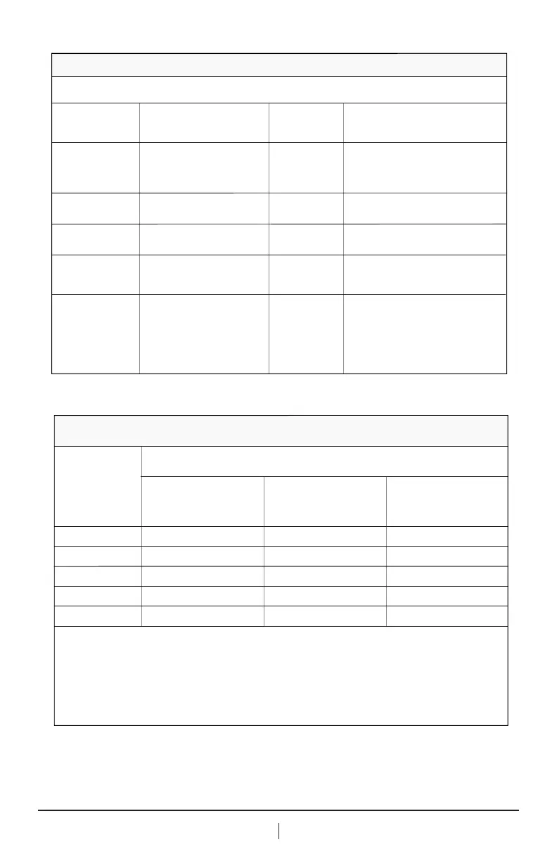
ELECTROMAGNETITC ENVIRONMENTCOMPLIANCE
LEVEL (OF THIS
DEVICE)
IEC 60601-1-2
TEST LEVEL
power supply lines: ± 2 kV
longer input / output lines: ± 1 kV
contact discharge: ± 6 kV
air discharge: ± 8 kV
Common mode: ± 2 kV
differential mode: ± 1 kV
3 A/m
power frequency
magnetic field 50/60
Hz
(IEC 61000-4-8)
voltage dips and short
interruptions on AC
mains input lines
(IEC 61000-4-11)
dip >95%, 0.5 periods
dip 60%, 5 periods
dip 30%, 25 periods
dip >95%, 5 seconds
surges on AC mains
lines
(IEC 61000-4-5)
electrical fast
transients / bursts
(IEC 61000-4-4)
electrostatic discharge,
ESD (IEC 61000-4-2)
IMMUNITY
AGAINST
This equipment is intended for use in the electromagnetic environment specified below. The user of this
equipment should assure that is used in such an environment.
ELECTROMAGNETIC IMMUNITY
For transmitters rated at a maximum output power not listed above, the recommended separation distance d in meters
(m) can be estimated using the equation applicable to the frequency of the transmitter, where P is the maximum output
power rating of the transmitter in watts (W) according to the transmitter manufacturer.
NOTE 1: At 80 MHz and 800 MHz, the separation distance for the higher frequency range applies.
NOTE 2: These guidelines may not apply in all situations. Electromagnetic propagation is affected by absorption and
reflection from structures, objects and people.
150 kHz – 80 MHz
d=1.2/V1]√P
80 MHz to 800MHz
d=1.2/V1]√P
800 MHz to 2.5 GHz
d=2.3√P
0.01
0.1
1
10
100
0.12 0.12
0.38
1.2
3.8
12
0.38
1.2
3.8
12
0.23
0.73
2.3
7.3
23
RATED
MAXIMUM
OUTPUT POWER
OF TRANSMITTER
W
Recommended separation distances between portable and mobile RF communications equipment
and the equipment
Separation distance according to frequency of transmitters in meters