Magnetic Field Build-up
When the voltage is switched on, a magnetic field is built up in the
brake coil, which attracts the armature disk to the coil carrier and
releases the brake.
Field Build-up with Normal Excitation
If we energise the magnetic coil with nominal voltage, the coil
voltage does not immediately reach its nominal value. The coil
inductivity causes the current to rise slowly as an exponential
function. Accordingly, the build-up of the magnetic field happens
more slowly and the braking torque drop (curve 1, below) is also
delayed.
Field Build-up with Overexcitation
A quicker and safer drop in braking torque is achieved if the coil
is temporarily placed under a higher voltage than the nominal
voltage, as the current then increases more quickly. Once the brake
is released, it is possible to switch to the nominal voltage (curve
2, below). The relationship between the overexcitation and the
separation time t
2
is roughly proportional indirectly; this means that
at doubled nominal voltage, the separation time t
2
for brake release
is halved. The ROBA
®
-switch fast-acting rectifier works on this
principle.
•
•
Current path
Braking torque path
I
nom
M
nom
Operation with overexcitation requires testing of:
- the necessary overexcitation time * (page 12)
- as well as of the RMS coil capacity ** for a cycle frequency higher
than 1 cycle per minute (page 12).
Electrical Connection and Wiring
DC current is necessary for the operation of the brake. The coil
voltage is indicated on the Type tag as well as on the brake body
and is designed according to the DIN IEC 60038 (± 10 % tolerance).
Operation is possible both via alternating voltage in connection
with a rectifier or with another suitable DC supply. Dependent on
the brake equipment, the connection possibilities can vary. Please
follow the exact connections according to the Wiring Diagram. The
manufacturer and the user must observe the applicable directives
and standards (e.g. DIN EN 60204-1 and DIN VDE 0580). Their
observance must be guaranteed and double-checked.
Earthing Connection
The brake is designed for Protection Class I. This protection
covers not only the basic insulation but also the connection of all
conductive parts to the PE conductor on the fixed installation. If the
basic insulation fails, no contact voltage will remain. Please carry
out a standardized inspection of the PE conductor connections to all
contactable metal parts.
Device Fuses
To protect against damage from short circuits, please add suitable
device fuses to the mains cable.
Switching Behaviour
The operational behaviour of a brake is to a large extent dependent
on the switching mode used. Furthermore, the switching times are
influenced by the temperature and the air gap between the armature
disk and the coil carrier (dependent on the wear condition of the
linings).
Switching Times
The values are mean values which refer to the nominal air gap and the nominal torque (100 %) for a warm brake.
For other braking torque adjustments, see Diagram: “Brake separation time t
2
dependent on spring configuration“ on page 12.
Switching Times
Size
2 4 8 16 32 60 100 150 250 500 1000
Nominal torque (100 %)
[Nm] 2 4 8 16 32 60 100 150 250 500 1000
Connection
time
DC-side switching
t
1
[ms] 10 18 20 30 50 55 68 80 100 100 180
AC-side switching
t
1
[ms] 100 160 220 320 400 500 640 730 1100 1100 1200
Response delay
on connection
DC-side switching
t
11
[ms] 6 12 16 25 35 35 38 40 50 30 70
AC-side switching
t
11
[ms] 80 130 175 240 300 350 400 450 700 700 750
Separation time
t
2
[ms] 28 30 45 70 100 150 180 220 290 400 270 *
Table 6
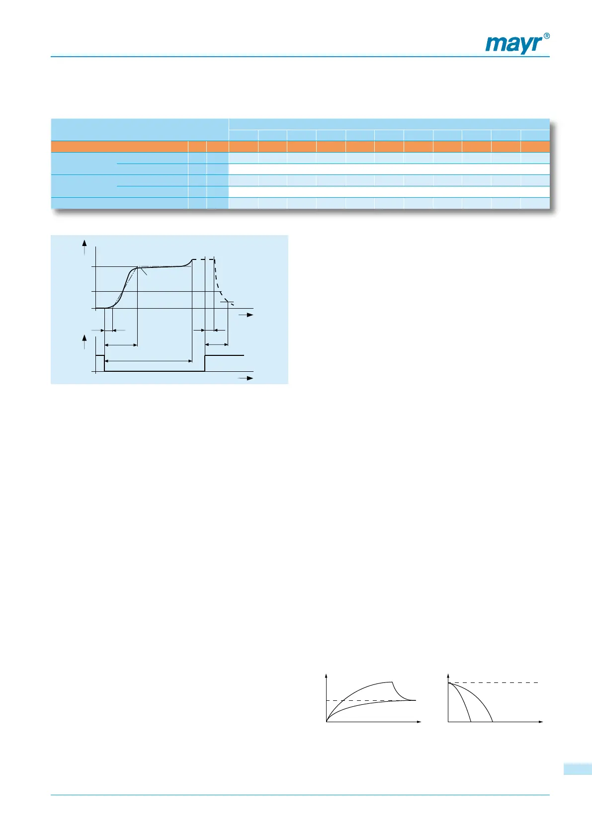
Diagram 5: Torque-Time
Key:
M
1
M
2
M
4
M
6
P
t
1
t
11
t
2
t
21
t
4
= Switching torque
= Nominal torque (characteristic torque)
= Transmittable torque
= Load torque
= Input power
= Connection time
= Response delay on connection
= Separation time
= Response delay on separation
= Total switch-on time + t
11
* Value in operation with overexcitation
ON
OFF
ROBA-stop
®
-M – Switching Times / Electrical Connection
M
M
2
M
6
M
1
t
11
t
1
t
4
P
t
21
t
2
M
4
0,1 M
2
t
t
1111
 Loading...