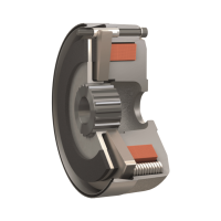
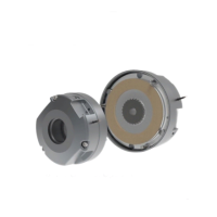
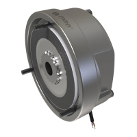
Application
Rectifiers are used to connect DC units to alternating voltage
supplies, for example electromagnetic brakes and clutches
(ROBA-stop
®
, ROBA-quick
®
, ROBATIC
®
), electromagnets,
electrovalves, contactors, switch-on safe DC motors, etc.
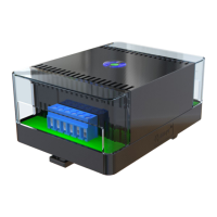
Function
The AC input voltage (VAC) is rectified (VDC) in order to operate DC
voltage units. Also, voltage peaks, which occur when switching off
inductive loads and which may cause damage to insulation and
contacts, are limited and the contact load reduced.
Electrical Connection (Terminals)
1 + 2 Input voltage
3 + 4 Connection for an external switch for DC-side switching
5 + 6 Coil
7 - 10 Free nc terminals (only for size 2)
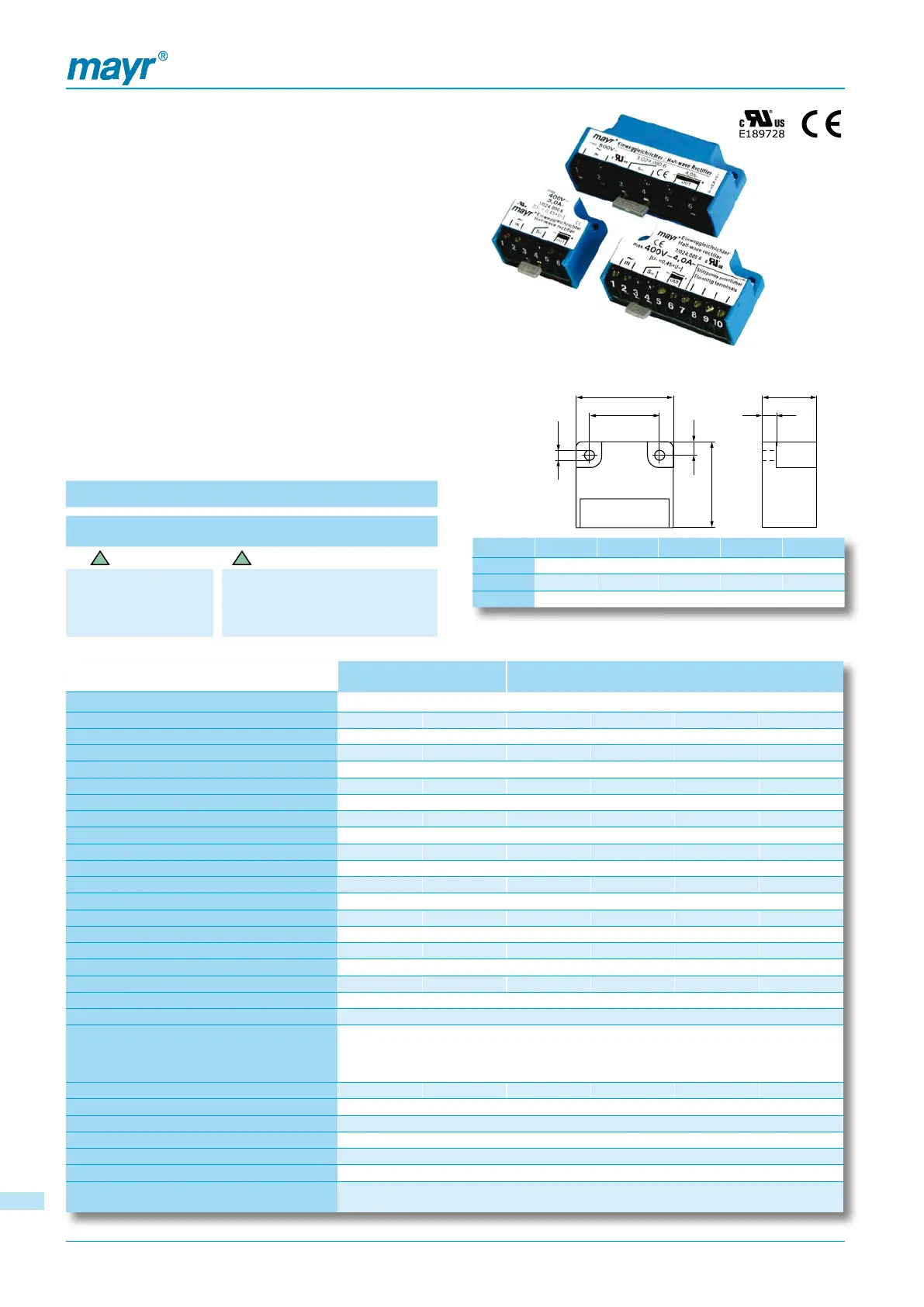
Dimensions (mm)
Order Number
__ / 0 2 __ . 0 0 0 . 6
Size
1
up to
4
4
5
Half-wave rectifier
Bridge rectifier
Size A B C ØD E
1 34 30 25 3,5 4,5
2 54 30 44 4,5 5,0
3/4 64 30 54 4,5 5,0
Technical Data
Bridge rectifier Half-wave rectifier
Calculation output voltage
VDC = VAC x 0,9 VDC = VAC x 0,45
Type 1/025 2/025 1/024 2/024 3/024 4/024
Max. input voltage 230 VAC 230 VAC 400 VAC 400 VAC 500 VAC 600 VAC
Max. output voltage 207 VDC 207 VDC 180 VDC 180 VDC 225 VDC 270 VDC
Output current at ≤ 50°C 2,5 A 2,5 A 3,0 A 4,0 A 4,0 A 4,0 A
Output current at max. 85 °C 1,7 A 1,7 A 1,8 A 2,4 A 2,4 A 2,4 A
Max. coil capacity at 115 VAC ≤ 50 °C 260 W 260 W - - - -
Max. coil capacity at 115 VAC up to 85 °C 177 W 177 W - - - -
Max. coil capacity at 230 VAC ≤ 50 °C 517 W 517 W 312 W 416 W 416 W 416 W
Max. coil capacity at 230 VAC up to 85 °C 352 W 352 W 187 W 250 W 250 W 250 W
Max. coil capacity at 400 VAC ≤ 50 °C - - 540 W 720 W 720 W 720 W
Max. coil capacity at 400 VAC up to 85 °C - - 324 W 432 W 432 W 432 W
Max. coil capacity at 500 VAC ≤ 50 °C - - - - 900 W 900 W
Max. coil capacity at 500 VAC up to 85 °C - - - - 540 W 540 W
Max. coil capacity at 600 VAC ≤ 50 °C - - - - - 1080 W
Max. coil capacity at 600 VAC up to 85 °C - - - - - 648 W
Peak reverse voltage 1600 V 1600 V 2000 V 1600 V 2000 V 2000 V
Rated insulation voltage 250 V
RMS
320 V
RMS
500 V
RMS
500 V
RMS
630 V
RMS
630 V
RMS
Pollution degree (insulation coordination) 2 2 2 1 2 2
Protection fuse To be included in the input voltage line.
Recommended microfuse switching capacity H
The microfuse corresponds to the max. possible connection
capacity. If fuses are used according to the actual capacities,
please observe the permitted limit integral I²t on selection.
FF 3,15A FF 3,15A FF 4A FF 5A FF 5A FF 5A
Permitted limit integral l
2
t 40 A
2
s 40 A
2
s 50 A
2
s 100 A
2
s 50 A
2
s 50 A
2
s
Protection IP65 components, encapsulated / IP20 terminals
Terminals Cross-section 0,14 - 1,5 mm
2
(AWG 26-14)
Ambient temperature - 25 °C up to + 85 °C
Storage temperature - 25 °C up to + 105 °C
Conformity markings UL, CE UL, CE UL, CE UL, CE UL, CE CE
Installation conditions
The installation position can be user-defined. Please ensure sufficient heat dissipation
and air convection! Do not install near to sources of intense heat!
Half-wave Rectifiers and Bridge Rectifiers Type 02_.000.6
Accessories: Mounting bracket set for 35 mm rail acc. to
EN 50022: Article-No. 1803201
1414
 Loading...