Installation and Operational Instructions for
ROBA-stop
®
-S brake Type 856. _ _ _ . _
Sizes 8, 9 and 10 (B.8.3.GB)
03/11/2010 TK/KE/GC/SU Chr. Mayr GmbH + Co. KG Tel.: 08341 / 804-0
Eichenstraße 1 Fax: 08341 / 804-421
D-87665 Mauerstetten http://www.mayr.de
Page 12 of 14 Germany E-Mail: info@mayr.de
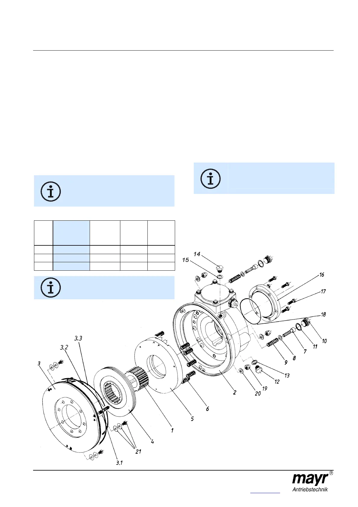
Braking Torque Adjustment (Fig. 14)
Braking torque adjustment is carried out via various thrust spring
(6) assembly variants in the coil carrier (2) acc. Table 2.
Procedural Method:
1. Unscrew the screw plugs (10) inc. the copper sealing rings
(11).
2. Screw in both emergency release screws (7) up to contact
on the coil carrier (2)
3. Loosen the cap nuts (19) inc. the washers (20).
4. Remove the brake from the flange plate (3).
Do not damage the O-rings (3.2 and 3.3)!
5. Remove the emergency release screws (7).
6. Remove the armature disk (5).
7. Remove abraded particles from the rotor and clean the
brake.
Do not use grease or oil.
8. Change the number of thrust springs (6) acc. Table 2.
The thrust springs must be distributed evenly in
the coil carrier (2). Always remove or insert two
springs located opposite each other to make
sure that the armature disk (5) is loaded evenly.
Only use mayr
®
thrust springs!
Table 2: Spring Configuration
Size
Nominal
torque 10
springs
[Nm]
8 springs
[Nm]
6 springs
[Nm]
4 springs
[Nm]
8
100 80 60 40
9
200 160 120 80
10
400 320 240 160
Torque tolerance: +40 % / -20 %
Further spring configurations or braking torques
on request.
9. Insert the armature disk (5).
Please make sure that the two pins for actuating the
microswitch situated next to each other protrude into the
terminal box.
10. Screw both emergency release screws (7) into the armature
disk (5) up to contact on the coil carrier (2).
If necessary, push the armature disk lightly onto the coil
carrier, so that the emergency release screws can be joined.
11. Push the brake over the stud screws (3.1) and join it with the
flange plate (3).
Do not damage the O-rings (3.2 and 3.3)!
12. Screw on the brake using the cap nuts (19) and the washers
(20).
Do not tilt!
Observe the tightening torque acc. Table 1!
13. Important!
Unscrew both emergency release screws (7) in
the armature disk (5).
Unscrew the screws, but do not remove them.
14. Screw the screw plugs (10) inc. the copper sealing rings
(11) back in. The emergency release screws (7) are spring
applied.
Fig. 14