Installation and Operational Instructions for
ROBA-stop
®
-S brake Type 856. _ _ _ . _
Sizes 8, 9 and 10 (B.8.3.GB)
03/11/2010 TK/KE/GC/SU Chr. Mayr GmbH + Co. KG Tel.: 08341 / 804-0
Eichenstraße 1 Fax: 08341 / 804-421
D-87665 Mauerstetten http://www.mayr.de
Page 6 of 14 Germany E-Mail: info@mayr.de
Design
ROBA-stop
®
-S brakes are spring applied, electromagnetic safety
brakes.
When installed, the ROBA-stop
®
-S brakes are completely closed
and therefore comply with Protection IP 67.
Standard equipment: - Microswitch for release monitoring
- Emergency hand release
- Condensate drain screw
- Air gap checks opening
- Tacho attachment possibility
Options: - Installed rectifier
- Microswitch for wear inspections
- Anti-condensation heating
Function
Spring applied function:
In de-energised condition, thrust springs (6) press against the
armature disk (5). The rotor (4) is held between the armature
disk (5) and the flange plate (3).
The shaft is braked via the gear hub (1).
Electromagnetic function:
Due to the magnetic force of the coil in the coil carrier (2), the
armature disk (5) is attracted against the spring force to the coil
carrier (2).
The brake is released and the shaft can rotate freely.
Safety brake function:
The ROBA-stop
®
-S brakes reliably and safely in the event of a
power switch-off, a power failure or an EMERGENCY STOP.
State of Delivery (Figs. 1 - 4)
The ROBA-stop
®
-S brake is pre-assembled and screwed
together with the flange plate (3).
The emergency release screws (7) are screwed into the
armature disk (5) and serve as a shipping brace.
The Technical Data is stated on the Type tag (25).
Please check state of delivery!
Installation Conditions
Before installing the ROBA-stop
®
-S brake, please observe the
following points:
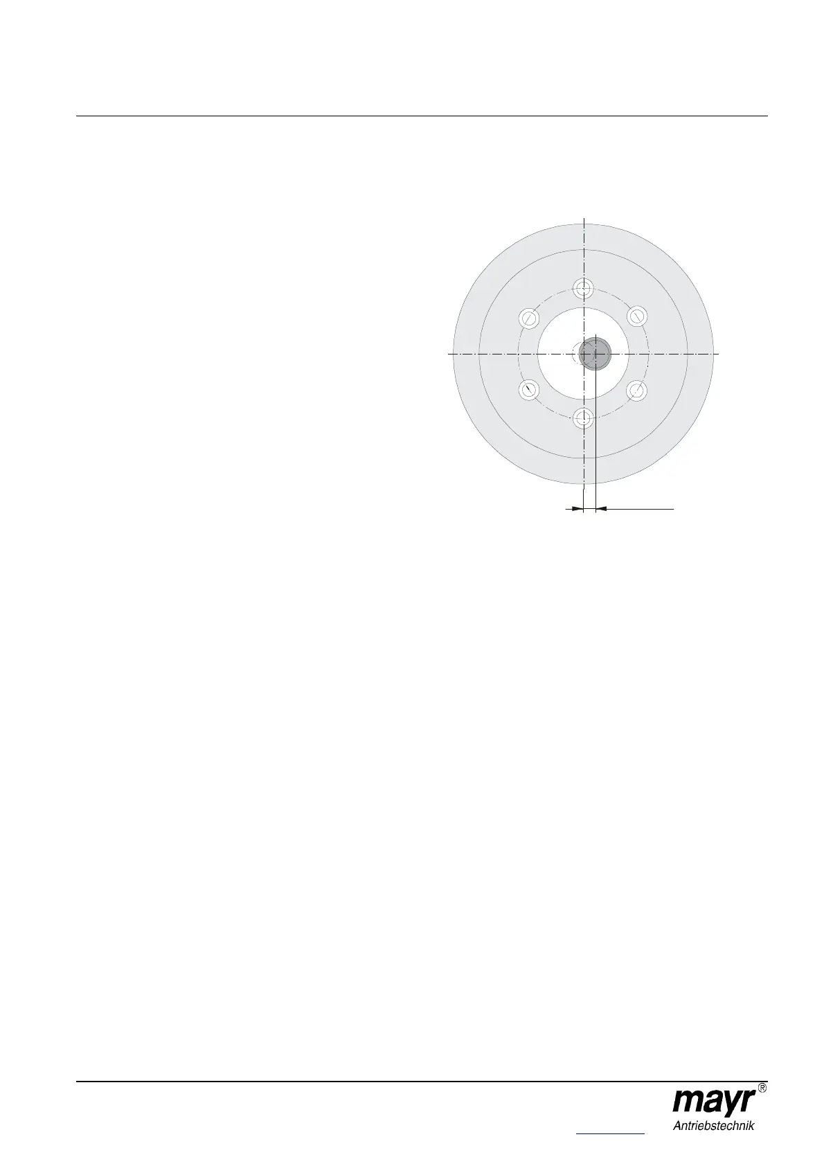
The eccentricity of the shaft end in relation to the mounting
pitch circle must not exceed 0,4 mm (Fig. 5).
Fig. 5
The axial run out deviation of the screw-on surface to the
shaft must not exceed the permitted axial run out tolerance
according to DIN 42955.
Larger deviations can lead to a drop in torque, to continuous
slipping on the rotor and to overheating.
The tolerances of the hub (8) and the shaft must be selected
so that the hub toothing (1) is not widened (please observe
the max. joining temperature of +200 °C). Widening of the
toothing leads to the rotor (4) jamming on the hub (8) and
therefore to brake malfunctions (recommended hub - shaft
tolerance H7/k6).
The rotor and brake surfaces must be oil and grease-free.
Please abstain from using cleaning agents containing
solvents, as they could affect the friction material.