Installation and Operational Instructions for
ROBA-stop
®
-S brake Type 856. _ _ _ . _
Sizes 8, 9 and 10 (B.8.3.GB)
03/11/2010 TK/KE/GC/SU Chr. Mayr GmbH + Co. KG Tel.: 08341 / 804-0
Eichenstraße 1 Fax: 08341 / 804-421
D-87665 Mauerstetten http://www.mayr.de
Page 7 of 14 Germany E-Mail: info@mayr.de
Brake Attachment
1. Loosen the cap nuts (19) and remove the washers (20).
2. Remove the flange plate (3) from the brake by lightly tapping
the stud screws (3.1) with a plastic hammer.
3. Screw the flange plate (3) onto the motor bearing shield or
onto the machine wall (sealing must be carried out customer-
side; if there are any questions concerning sealing, please
contact the manufacturers).
4. Mount the gear hub (1) onto the shaft, bring it into the correct
position (the length of the key should lie over the entire hub)
and secure it axially (e.g. using a locking ring).
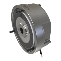
5. Push the rotor (4) by hand onto the gear (1).
Check that the toothing moves easily.
Do not cause any damage!
The rotor (4) must be placed onto the hub (1)
so that the toothing remains engaged even
after wear on the friction linings (Fig. 6).
Fig. 6
6. Push the brake over the stud screws (3.1) and join it with the
flange plate (3).
Do not damage the O-rings (3.2 and 3.3)!
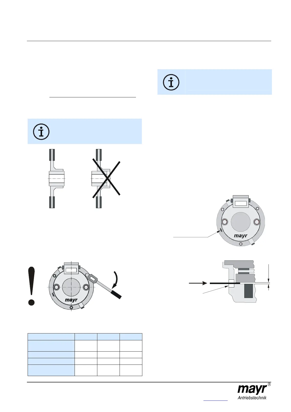
7. Screw on the brake using the cap nuts (19) and the washers
(20). Do not tilt!
Observe the tightening torque acc. Table 1!
Fig. 7
Table 1
Size 8 9 10
Tightening torque for
cap nuts (19) [Nm]
13
26
26
Nominal air gap [mm]
0,20
+0,25
0,25
+0,25
0,25
+0,25
Max. air gap [mm]
0,75 1,0 1,1
Min. air gap for
re-adjustment [mm]
0,65 0,8 0,8
8. Unscrew the screw plugs (10) inc. the copper sealing rings
(11).
9. Important!
Unscrew both emergency release screws (7) in
the armature disk (5).
Unscrew the screws, but do not remove them.
10. Screw the screw plugs (10) inc. the copper sealing rings (11)
back in. The emergency release screws (7) are spring
applied.
11. Check the air gap acc. section "Air Gap Inspection".
Air Gap Inspection (Figs. 8 and 9)
Due to wear on the friction linings, the air gap between the coil
carrier (2) and the armature disk (5) increases.
The wear condition of the rotor (4) can be monitored in regular
air gap inspections.
Air gap inspection on a de-energised brake.
Air gap inspection on a de-energised brake:
1. Unscrew the screw plug (12) inc. the copper sealing ring (13).
2. Check the air gap by means of a feeler gauge.
The air gap must lie between the nominal air gap and the
max. air gap. Once the max. air gap has been reached, the
air gap must be re-adjusted (see Table 1).
Fig. 8
Fig. 9
Air gap
inspection opening
inspection opening
Feeler gauge