Testing Procedures
!
WARNING
To avoid risk of electrical shock, personal injury or death; disconnect power to oven before servicing, unless
testing requires power.
16 16022498 Rev. 0
©2003 Maytag Appliances Company
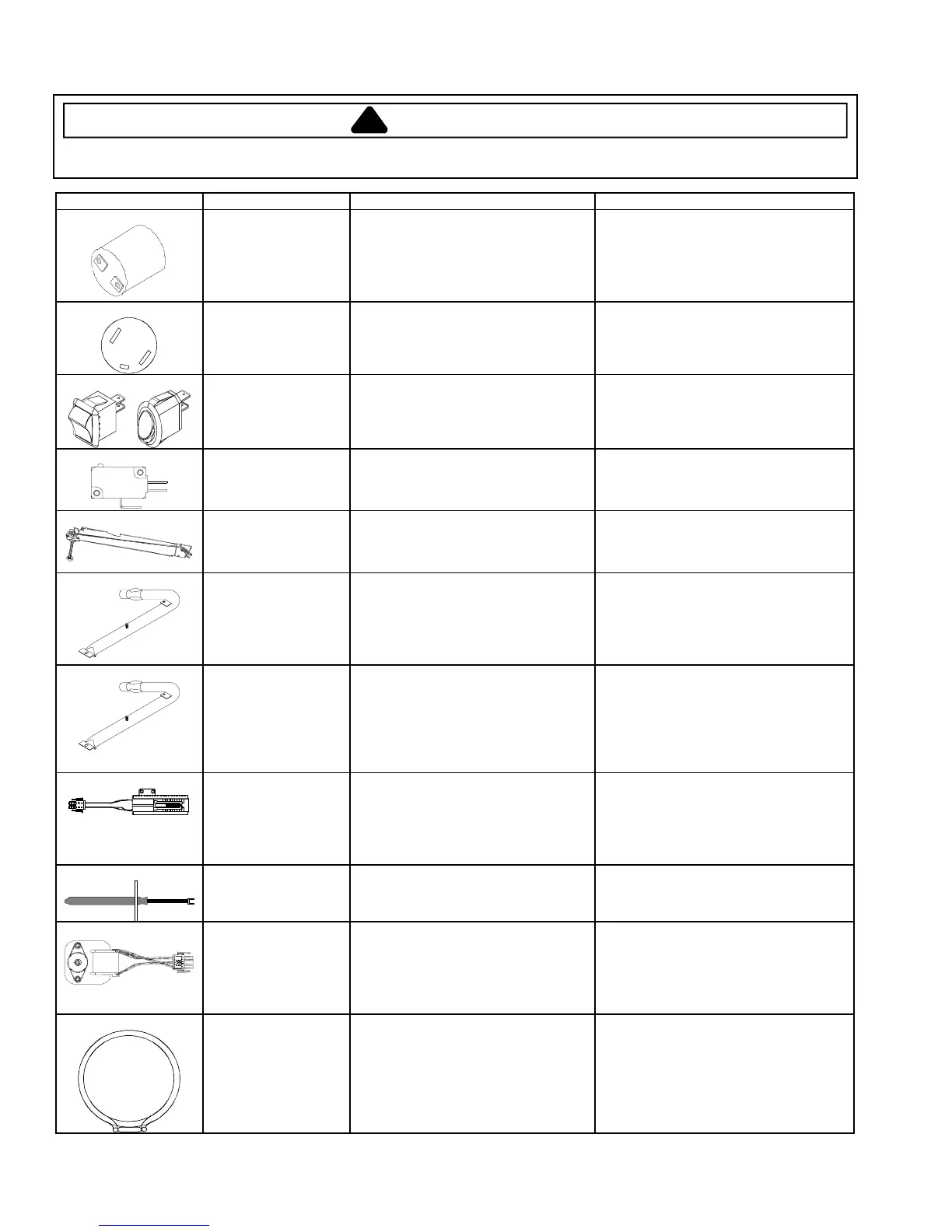
Illustration Component Test Procedure Results
Oven light socket Test continuity of receptacle terminals.
Measure voltage at oven light.
Indicates continuity with bulb screwed in.
120 VAC, see wiring diagram for terminal
identification.
If no voltage is present at oven light
check wiring.
NC
NO
C
Door plunger switch Remove switch from unit and measure
the following points:
C-NO
Plunger in continuity, Plunger out infinite.
Rocker switch Measure continuity of switch positions:
Closed ..............................................
Open.................................................
Continuity
Infinite
COM
NO
NC
Door light switch Switch connection in following
positions:
Not engaged
Engaged
Normally Open
COM-NO=Open, COM-NC=Closed
COM-NO=Closed, COM-NC=Open
Autolatch assembly
with switch
Disconnect wires and test for
continuity per wiring diagram.
See wiring diagram for schematic layout.
Refer to Parts Manual for correct
autolatch switch.
Bake burner Verify gas is supplied.
Orifice adjusted for Natural or LP.
Check for obstructions, contamination
in ports or damage.
Clean with hot soapy water and dry
completely.
Replace if punctured or torn.
Broil burner Verify gas is supplied.
Verify proper orifice installed for
Natural or LP.
Check for obstructions, contamination
in ports or damage.
Clean with hot soapy water and dry
completely.
Replace if punctured or torn.
Ignitor Test for voltage at terminals ...............
Test for the amount of amperage in the
circuit..................................................
(Ignitor may glow, but not have
sufficient amperage to open valve).
120 VAC
3.2
−3.6 Amps.
Temperature sensor Measure resistance.
Approximately 1100 Ω at room
temperature 80
ºF.
Convection motor fan Verify supply voltage ........................
Measure continuity at the following
points:
Terminal to terminal..........................
Terminal to ground...........................
120 VAC
Continuity
Infinite
Convection element Test continuity of terminals...............
Test voltage to terminals ..................
Approximately 14 Ω - cold
120 VAC