113249-2 Maytag Co. 11
Gas Information _______________________
!
WARNING
Explosion Hazard
Use a new CSA International approved gas supply line.
Install a shutoff valve.
Securely tighten all gas connections.
If connected to LP, have a qualified person make sure
gas pressure does not exceed 13” water column.
Examples of a qualified person include:
licensed heating personnel,
authorized gas company personnel, and
authorized service personnel.
Failure to do so can result in death, explosion, or fire.
Type of Gas
This dryer is equipped for use with natural gas. It is design-
certified by CSA International for L.P. (propane and butane)
gases with appropriate conversion (see below). No attempt
shall be made to convert the dryer from the gas specified on
the serial/rating plate for use with a different gas without
consulting the serving gas supplier. Conversion must be
done by a qualified service technician.
MLG35 L.P. Conversion Kit: 884448
It is your responsibility to have all plumbing connections,
materials, and workmanship conform to local and state
regulations or codes of the country of destination. In the
absence of such codes, all plumbing connections,
materials, and workmanship must conform to the applicable
local requirements. In the USA this is the National Fuel Gas
Code ANSI Z223.1-LATEST EDITION, or in Canada, the
Canadian Installation Codes CAN/CGA-B149.1-M91
(Natural Gas) or CAN/CGAB149.2-M91 (L.P. Gas) or LATEST
EDITION.
It is important that gas pressure regulators meet applicable
pressure requirements, and that gas meters be rated for
the total amount of all the appliance Btu being supplied.
For ease of service, the individual gas supply line of each
pocket must have its own manual shutoff valve.
The dryer and its individual shutoff valve must be
disconnected from the gas supply piping system during
any pressure testing of that system at test pressures in
excess of 1/2 psig (3.5 kPa).
Failure to isolate or disconnect the dryer from supply as
noted can cause irreparable damage to the gas valve,
voiding the warranty.
NOTE: Undersized gas piping will result in ignition
problems, slow drying, increased use of energy.
!
WARNING
Fire Hazard
Use 12 gauge solid copper wire.
Use a UL listed strain relief.
Connect the white wire to the white wire from the
electric service; Connect the black wire to the
black wire from the electric service; Connect the
green wire to the green wire from the ground
connection.
Securely tighten all electrical connections.
Failure to do so can result in death, fire, or
electrical shock.
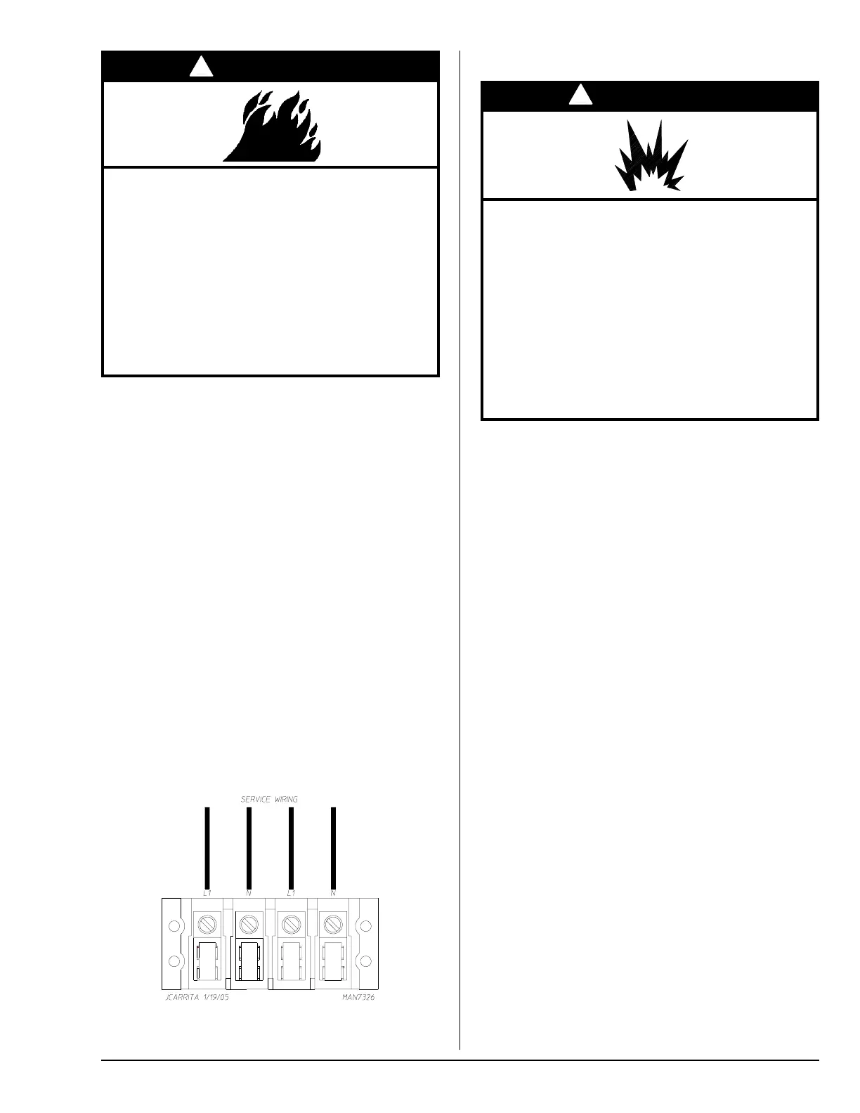
Single-Phase (1ø)
Wiring Connections / Hookup
The electrical input connections are made into the rear
service box located at the upper right area of the dryer. The
ground connection is made to the copper lug, also provided
in this box. To gain access, the service box cover must be
removed.
Insert incoming white wire (neutral) for the top pocket into
the far right hand connection.
Insert incoming black wire (L1) for the top pocket into the
second from the right connection.
Insert incoming white wire (neutral) for the bottom pocket
into the third from the right connection.
Insert incoming black wire (L1) for the bottom pocket into
the far left hand connection.
Insert both incoming green wires (ground) into the copper
lug.
Tighten strain relief screws assuring to leave a 1/2” of slack
in the box.
Replace electrical box plate by inserting 3 screws previously
removed.
120V Application with Neutral


 To Next Page