12 Maytag Co. 113249-2
The input ratings shown on the data label are for elevations
up to 2,000 feet (610 meters), unless elevation requirements
of over 2,000 feet (610 meters) were specified at the time
the dryer order was placed with the factory. The adjustment
or conversion of dryers in the field for elevations over 2,000
feet (610 meters) is made by changing each burner orifice.
If this conversion is necessary, contact the reseller who sold
the dryer or contact the manufacturer.
IMPORTANT: If connection to this appliance is made with
a flexible hose, it must be suitable for the appliance
category in accordance with national installation
regulations of the country of destination, and if in doubt
the installer must contact the supplier. The manufacturer
of this appliance does not recommend the use of flexible
gas supply line/hose.
In the U.S.A.: An individual manual shutoff valve must be
installed within 6 feet (1.8 meters) of the dryer in accordance
with the National Fuel Gas Code, ANSI Z223.1.
In Canada: An individual manual shutoff valve must be
installed in accordance with the B149.1, Natural Gas and
Propane Installation Code. It is recommended that an
individual manual shutoff valve be installed within 6 feet
(1.8 meters) of the dryer.
Gas Connections
Inlet connection .....1/2” N.P.T.
Inlet supply size ....1/2” Diameter Pipe (minimum)
Piping / Connections
The dryer is provided with two 1/2” N.P.T. inlet pipe
connections (1 for each tumbler) at the rear of the dryer. If a
separate feed is provided for each tumbler from the main
supply line (header), then a 1/2” (12.7 mm) line connection
is sufficient. However, if the top and bottom tumbler
connections are connected together, the supply from the
header must be increased to 3/4” (19.05 mm). There should
be a minimum 6-inch (15.24 cm) clearance between the
back guard and the first bend in the gas piping for ease of
servicing. It is recommended that a gas shutoff valve be
provided to the gas supply line of each dryer for ease in
servicing.
The size of the main gas supply line (header) will vary
depending on the distance this line travels from the gas
meter or, in the case of L.P. gas, the supply tank, other gas-
operated appliances on the same line, etc. Specific
information regarding supply line size should be determined
by the gas supplier.
GAS SPECIFICATIONS FOR CSA APPROVED 60 HZ DRYERS***
Gas Type and
Nominal Heating Value
Supply
Pressure
**Gross
Heat Input
Orifice Size
**Orifice
(Injector)
Quantity
Burner
Pressure
Btu/ft
3
in WC Btu/hr kW DMS mm in WC
Natural 1,000 7.0-13.0 64,000
18.74
23
3.912
13.5
*Liquid Propane 2,500 11.0 64,000
18.74
42
2.375
1 10.5
Heat Input / Gas Consumption / Orifice (Injector) Data
Shaded areas are stated in metric equivalents
* Gas valve’s internal regulator disabled.
** Information is per pocket/tumbler.
*** Consult factory for elevations over 2,000 feet (610 meters) for correct orifice size.
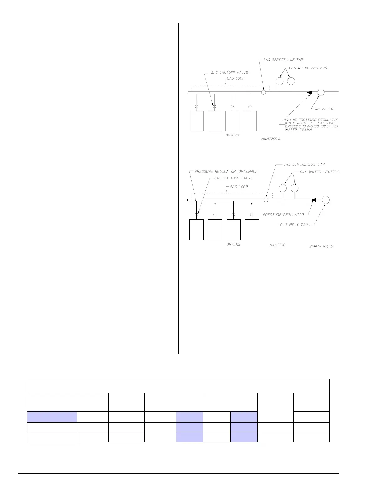
Consistent gas pressure is essential at all gas connections.
It is recommended that a 3/4” (19.05 mm) pipe gas loop be
installed in the supply line servicing a bank of dryers. An
in-line pressure regulator must be installed in the gas supply
line (header) if the (natural) gas pressure exceeds 13.0 in
WC (32.34 mb) pressure.
A plugged tap, accessible for a pressure gauge connection,
must be installed in the main gas supply line immediately
upstream of the dryers.
IMPORTANT: Pipe joint compounds that resist the action
of natural, L.P., and butane gases must be used.
Test all connections for leaks by brushing on a soapy
water solution (liquid detergent works well).
TYPICAL L.P. GAS INSTALLATION
NOTE: Undersized gas supply piping can create a low or
inconsistent pressure, which will result in erratic operation
of the burner ignition system.
TYPICAL NATURAL GAS INSTALLATION
 Loading...