IMPORTANT NOTES:
UNIT MUST BE DISCONNECTED FROM ELEC-
TRICAL OUTLET WHEN MAKING REPAIRS, RE-
PLACEMENTS, ADJUSTMENTS AND CONTIN-
UITY CHECKS. WAIT AT LEAST ONE MINUTE,
UNTIL THE HIGH VOLTAGE CAPACITOR IN THE
HIGH VOLTAGE POWER SUPPLY HAS FULLY
DISCHARGED.
THE CAPACITOR SHOULD BE DISCHARGED BY
USING INSULATED WIRE - I.E. TEST PROBE
CONNECTED TO 10K-OHM RESISTOR IN SERIES
TO GROUND.
WHEN RECONNECTING THE WIRE LEADS TO
ANY PART, MAKE SURE THE WIRING CONNE-
CTIONS AND LEAD COLORS ARE CORRECTLY
MATCHED ACCORDING TO THE OVERALL CIR-
CUIT DIAGRAM. (ESPECIALLY SWITCHES AND
HIGH VOLTAGE CIRCUIT.)
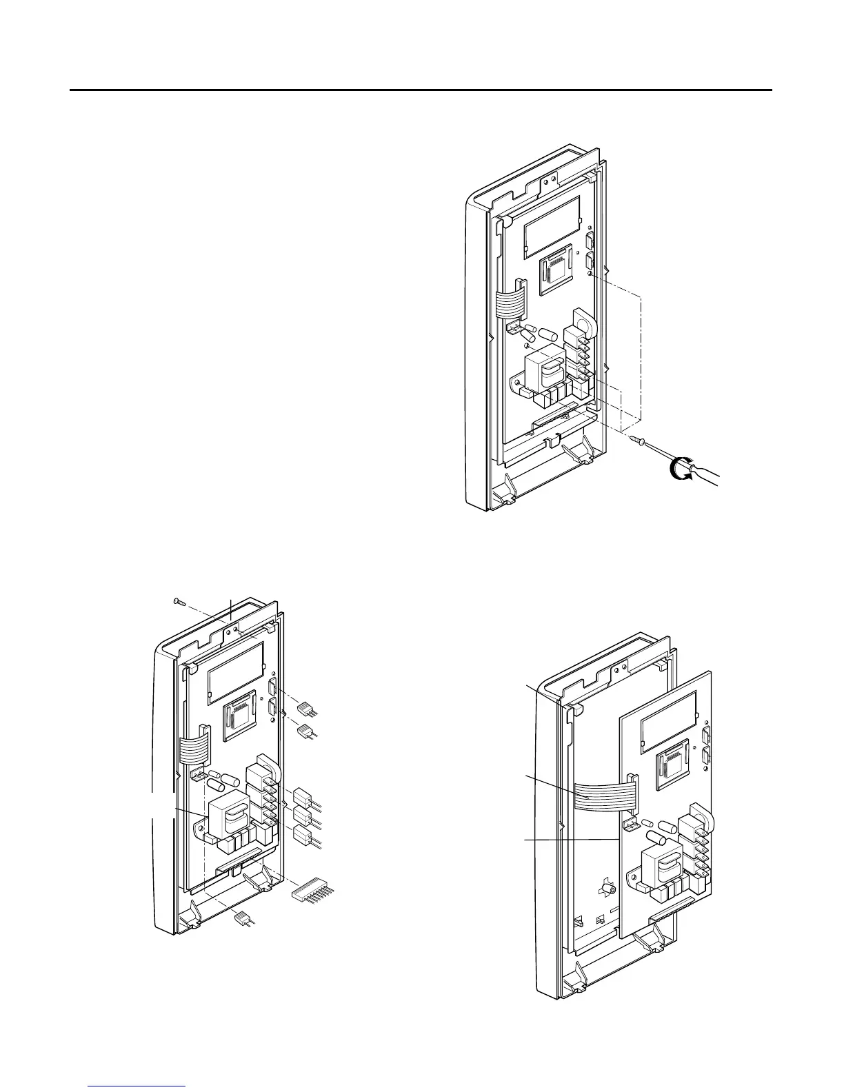
A. REMOVING POWER AND CONTROL
CIRCUIT BOARD (Figures 1, 2 and 3)
(1) Remove a screw securing the control panel
assembly to the oven cavity.
(2) Remove the control panel with pushing it upward.
(3) Remove the three connectors (CN1, CN2, CN4,
CN5) and wire leads (Relay8, Relay10, Relay11)
from the circuit board.
(4) Remove 3 screws securing the circuit board.
(5) Remove the FPC connector from the terminal
socket following “HOW TO REMOVE THE FPC
CONNECTOR” on the next page.
(6) Remove the circuit board from the control bracket
carefully.
7-4
DISASSEMBLY INSTRUCTIONS
 Loading...