McCain ATC eX NEMA Controller – User Manual 3
Version 1.0
2 THE ATC eX NEMA CONTROLLER
2.1 Overview
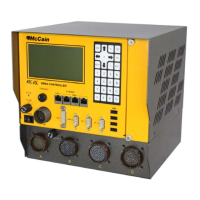
The ATC eX NEMA controller unit is designed to meet TS2-2-2003 standard Ver 02.06, ATC 5.2b.
The controller unit uses an engine board fully compatible to ATC 5.2b standard; with the MPC8360 core
at 400MHz, 128MB DRAM, 16MB FLASH and 2MB SRAM.
All ATC eX NEMA controller’s interfaces to the cabinet, to other external devices, or to the user are
accessible from the front panel.
The unit has three RS-232 asynchronous serial communication ports with software selectable speed from
1.2Kbps to 115.2Kbps, these ports are available over DB-9 male connectors. PORT 2 is used primarily
for connecting a terminal computer, or as a general purpose port. SP-5 and SP-8 are general purpose
ports but only SP-8 has modem control lines (RTS, CTS, DCD).
An SDLC port is designated to synchronous communications to cabinet’s serial bus, it is a RS-485 serial
communication port with software selectable speed from 19.2Kbps to 614Kbps available over a DB-15
female connector.
A 2070 compatible modem or expansion slot is available to use SP-1 and SP-2 serial ports. This slot
works similar to 2070 controller slot A2.
Serial communications will be either synchronous or asynchronous depending on the type of board used
(2070-7A, 2070-7B, 2070-6A, 2070-6B, etc). Speed for this port is also software selectable from 1.2Kbps
to 115.2Kbps when it is operating on asynchronous mode and from 19.2Kbps to 614.4Kbps when it
operates on synchronous mode.
The unit also has 4 high speed USB ports to download and upload databases. These 4 ports are
connected directly to a USB hub and one port is routed to ATC Engine.
Two 100MBPS Ethernet ports are provided for communicating with a central, connecting to peripheral
devices, and also for operating as a remote terminal to download/upload files, updates, log files, etc.
The interface for the user is an LCD with backlight and a 28-keys keypad to enter/retrieve all information
about the status of the controller’s or traffic application. A contrast knob is used to adjust the contrast as
desired for user’s optimal view.
ACTIVE LED shows the status of the controller’s traffic application.
A circular connector A2 used to supply the AC input and fault monitor signals when required.
A rocker switch is used for turning ON and OFF the controller.
An AC line fuse holder for a 2A fuse with front access and removal without tools feature.
The functionality of the several modules/sub-assemblies which conform the controller unit is described in
the below sections.

 Loading...