17
MACHINE SET-UP & ADJUSTMENT
Machine set-up and adjustments must always be performed on a firm level
site with Robocut engine switched off and the starting key removed.
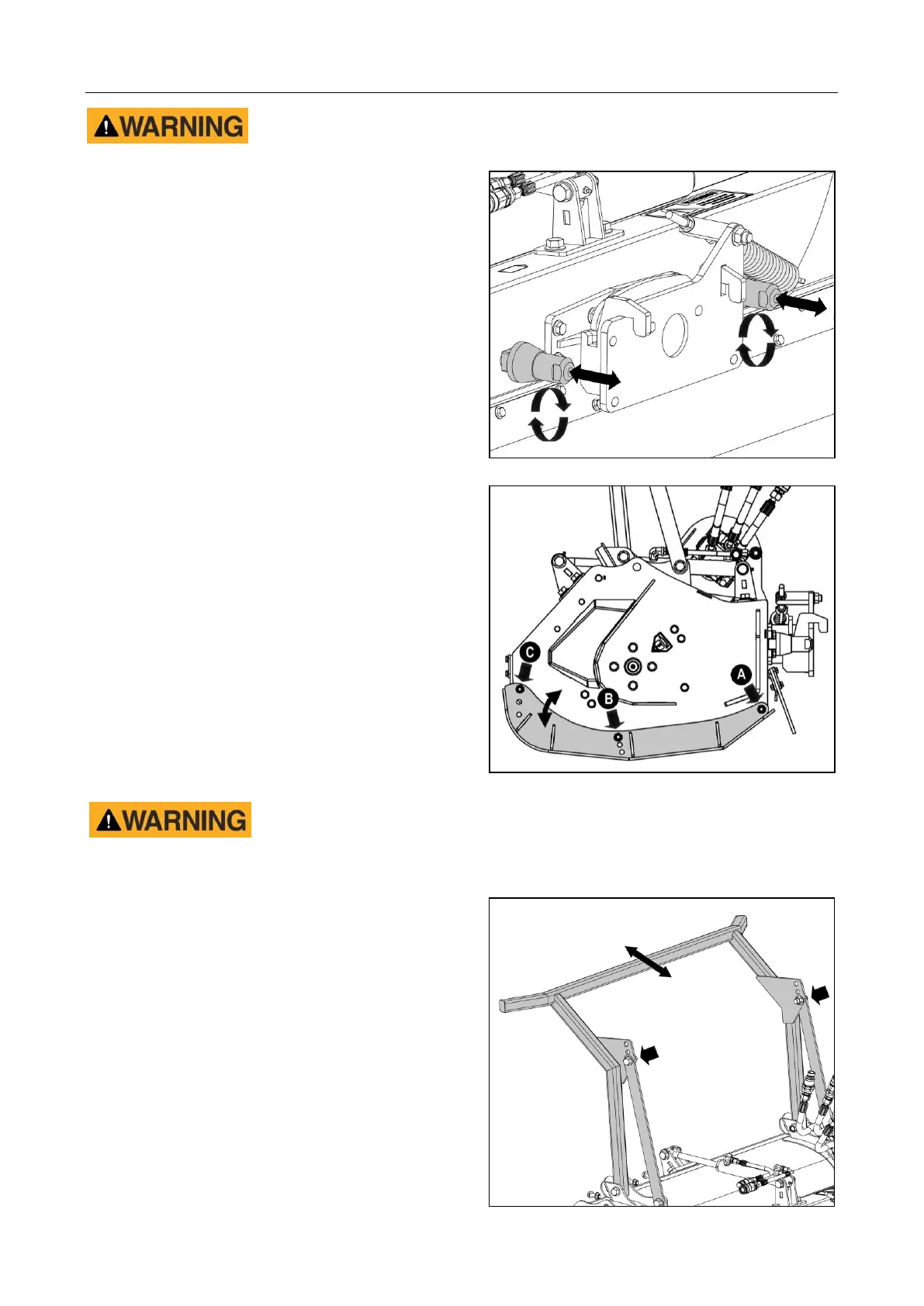
Lateral Supports (Thrust Pins)
The rear casing of the machine is fitted with
thrust pins on each side of its mounting; these
are to provide lateral support in the event of
accidental impact, thus reducing stress on the
central mounting point.
When mounting the machine, the thrust pins
must be adjusted to place them in touch
contact with the Robocut’s frontal mounting
plate. Adjustment is performed by rotating the
pins to extend them until they are in contact
with the mounting plate.
Skids Adjustment
Machines are equipped with adjustable skids
on each side of the machine which can be set
at any one of 3 height positions; the height
setting chosen will determine the cutting height
of the rotor.
To adjust the skid height the rear bolt ‘A’ must
be slackened off and the frontal bolts ‘B’ & ‘C’
removed; this will allow the front of the skid to
be pivoted into a higher or lower position. With
the height setting selected; replace bolts ‘B’
and ‘C’ before fully tightening all 3 bolts.
Repeat the procedure on the opposing skid
ensuring the same exact same height position
is selected.
Never attempt to use the machine with the side skids removed; flails
should not be allowed to contact the ground. Do not attempt to adjust skid
heights whilst the machine is running.
Push Bar Adjustment
Machines are equipped with a push bar; this
aids the feeding of material into the machine
by forcing it forward and downward ahead of
the rotor. The position of the push bar can be
adjusted to suit the requirement of the job.
Adjustment of the push bar is achieved by
removal of the nuts and bolts from the upper
positions of the support bars and replacing
them in alternate hole positions to change the
work angle.
Ensure when replacing fixings that the same
hole position is selected on each support.