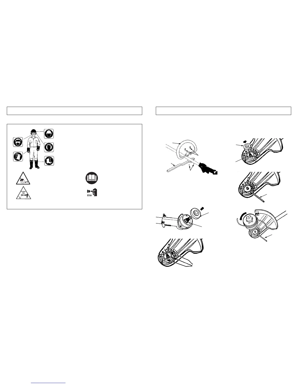
3-1. “P” HANDLE ASSEMBLY
1. To install handle onto unit, you will need the following
components from your user kit: “P” handle (A & B),
screws (C) and nuts (D). (Figure 3-1).
2. Install the handle (B) on the shaft 6.0" to 7.87" (160-
200mm) fromthrottle and tighten the 2 screws (C) and nuts (D).
3-2. DEBRIS SHIELD
1. Remove gear collar (A) from the threaded gear hous-
ing shaft. Ensure collar spacer (B) is in place (Fig. 3-
2A).
2. Install debris shield with 3 screws (C) provided (Fig. 3-
2B).
3-3. STRINGHEAD INSTALLATION
1. Install gear collar (A) ensuring that COLLAR SPACER
(B) is in place (Fig. 3-3A).
2. Insert holding pin (C) and thread stringhead onto
shaft. Tighten stringhead by HAND ONLY (Fig. 3-3B
and 3-3C).
6 7
2 - SAFETY PRECAUTIONS 3 - ASSEMBLY INSTRUCTIONS
Use of these personal safety items is highly recommended to
reduce the risk of accidental injury.
Minimum operating distance
2-3. INTERNATIONAL SYMBOLS
Read the User Manual.
Pump the primer bulb 10 times.
3-1A
A
B
C
D
3-2A
A
B
3-2B
C
3-3A
3-3B
3-3C
A
B
C
C