7
1. Gearcase notch
2. Handle lock
3. Handle (high po si tion)
4. Shift lever
5. Handle (low position)
6. Handle lock lever
2. Assembly 2. Zusammenbau
2. Montage 2. Montaje
2. Montaggio 2. Montering
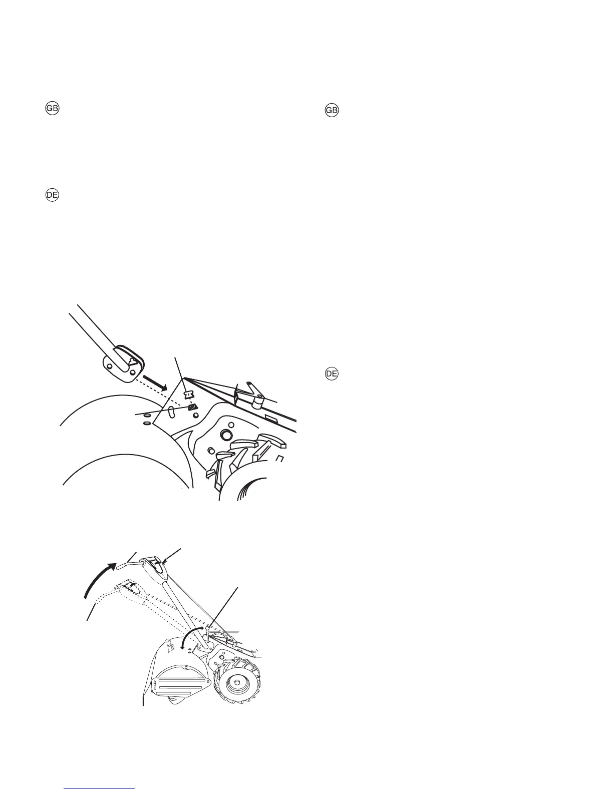
Install handle
a. Insert one handle lock (with teeth facing outward) in
gearcase notch (fig. 1). Apply grease on smooth side of
handle lock. This will aid in keeping lock in place until
handle is lowered into postion.
b. Grasp handle assembly, ease han dle base into "up" posi-
tion as shown in figure 2. Be sure handle lock remains
in gearcase notch. Be careful not to stretch or kink
cables.
c. Rotate handle assembly down. Insert rear carriage bolt
(fig. 3-inset) first, with head of bolt on L.H. side of tiller.
Insert front pivot bolt. Lower the handle as sem bly. Tighten
bolts so han dle moves with some resistance.
d. Insert second handle lock (with teeth facing inward) in
slot handle base (fig. 3-inset).
e. Place washer on threaded end of handle lock lever.
f. Insert handle lock lever through handle base and gear
case (fig. 3-inset).
g. With handle assembly in lowest position, securely tight en
handle lock lever by rotating clock wise.
1
2
Figure 1
Figure 2
1. Getriebegehäuse-Aussparung
2. Handgriffsperre
3. Handgriff (obere Stellung)
4. Schalthebel
5. Handgriff (untere Stellung)
6. Hangriffsperrenhebel
Montage des Handgriffs
a. Eine Handgriffsperre (mit den Zähnen nach außen) in die
Aussparung des Getriebegenhäuses einpassen (Abb. 1).
Die glatte Seite der Handgriffsperre mit Fett schmieren.
Auf diese Weise wird die Sperre in der Aussparung ge-
halten, bis der Griff angebracht worden ist.
b. Handgriff fassen und die Handgriffplatte gemäß (Abb. 2)
in die obere Stellung bringen. Kontrollieren, ob sich die
Handgriffsperre noch in der Aussparung des Getriebege
häuses befindet. Kabel dürfen nicht gestreckt oder ver-
heddert werden.
c. Den Handgriff nach unten schwenken. Den hinteren Bol-
zen (abb. 3 ausschnitt) mit dem Bolzenkopf auf die linke
Seite der Bodenfräse gerichtet, zuerst anbringen. Den
vorderen Gelenkbolzen einsetzen. Hangriffmontagesatz
senken. Die Bolzen so festziehen, daß die Handgriffe
beim Bewegen etwas Widerstand leisten.
d. Die andere Handgriffsperre (mit den Zähnen nach innen)
in den schiltz der Handgriffplatte einpassen (abb. 3 aus-
schnitt).
e. An dem mit Gewinde versehenen Ende des Handgriffs
perrenhebels eine Unterlegscheibe anbringen.
f. Handgriffsperrenhebel durch die Handgriffplatte und das
Getriebegehäuse stecken (Abb. 3 ausschnitt).
g. Mit dem Handgriff in der untersten stellung, ist der
Handgriffsperrenhebel durch Drehen im Uhrzeigersinn
festzuziehen.
Abb. 1
Abb. 2
3
4
5
6
 Loading...