SERVICE MANUAL
Performance Specifications ........................................ 2
Notes ......................................................................... 2
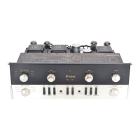
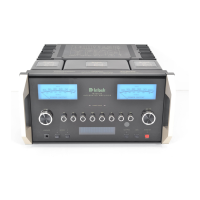
Rear Panel .................................................................. 3
Section Location ........................................................ 4
Block Diagram ...................................................... 5 - 7
Interconnection Diagram .................................... 8 - 10
Main Schematic and PCB................................. 11 - 16
Control Schematic and PCB ............................. 17 - 20
Balanced Schematic and PCB ........................... 21 - 22
Volume/Tone Schematic and PCB ..................... 23 - 26
Data Schematic and PCB................................... 27 - 28
Pushbutton Schematic and PCB ........................ 29 - 30
Amplifier Schematic and PCB............................ 31 - 34
Power Supply Schematic and PCB..................... 35 - 38
Meter Schematic and PCB ................................. 39 - 40
Backup PS Schematic and PCB ................................ 41
Terminal Schematic and PCB ................................... 42
Parts List ............................................................ 43 - 48
Exploded View and Parts List ............................. 49 - 52
Repacking Instructions ............................................. 53
CONTENTS
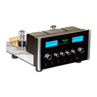
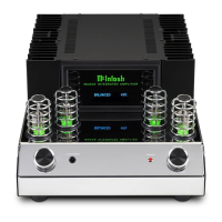
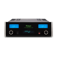
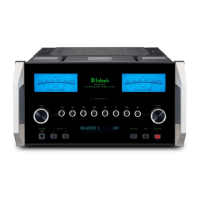
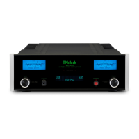
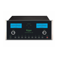
TUBE
INTEGRATED AMPLIFIER