SCHEMATIC NOTES
MA
5100
Unless otherwise specified: Resistance values are in ohms, 1/2 watt, and 10%
tolerance;
capacitance
values
smaller
than
1 are in
microfarads
(mfd);
capacitance
values greater than 1 are in picofarads (pF) ; inductors are in microhenries (µH).
Printed
circuit
board
components
are
outlined
on the
schematics
by
dotted
lines.
The
circled
numbers
on the
dotted
lines
correspond
to the
numbers
of the PC
board
layouts.
The
heavy
lines
on the
schematics denote
the
primary
signal
path.
The terminal numbering of rotary switches is for reference only.
All
voltages
indicated
on the
schematics
are
measured
under
the
following
condi-
tions :
a. Use of an 11
megohm
input
impedance
VTVM,
b. All
voltages
±10%
with
respect
to
chassis
ground.
c. No signal at input terminals,
d. AC
input
at 117
volts
AC,
50/60Hz.
e. Front panel controls at:
Input
Selector
Mode Selector
AUX
STEREO
Volume
Power
MAX
ON
All other controls in normal position.
1. In
units
with
serial
numbers below
46H01,
the
output
monitor
PC
board
is not
used.
2. In
units
with
serial
numbers below 44H50:
R256
&
R25?
are not
used;
R254 &
R255
are 120
ohms;
transistors
Q205
& Q206
(132-021)
and
pots R221
&
R222
(134-120)
are
used;
the
emitter
of
Q2l5
&
Q216
is
connected
as
shown
by the
dotted
line;
C221
&
C222
are
used.
3. In
early
units,
C5 & C6
were
39pF.
4. In
units
with
serial
numbers below 30H15: L201, L202, R241,
R242,
C215,
C216, C217, and C2l8 are not used; C227, C228, C229, C230, C231, and C232
are used; R229 & R230 are 100 ohms; C201 & C202 are 330pF.
5. In
early
units,
C207
&
C208
were
200µF,
3V
(part
number 066-086).
6. In
units
with
serial
numbers below 30H30: D201
&
D202
were
two
diodes
(part number 070-022).
7. In
units
with
serial
numbers below 28H00:
C3,
C4
}
C5, C6, R9,
R10,
and
R314 are not used.
8. In
early
units,
C308
&
C309
were
10,000µF,
40V
(part
number 066-090).
9. In
units
with
serial
numbers below 24H05:
R237
&
R238
are .47
ohms;
R233
&
R234
are 220
ohms;
C211, C212, C213,
and
C2114
are
.01µF.
10. In
units
with
serial
numbers below
23H7S:
D211, D212, D213,
and
D214
are
not used.
11. In
units
with
serial
numbers below 22H00:
R227
&
R228
were
1K,
10%,
1W,
12. In
units
with
serial
No's below 54H60:
R254
and
R255
are 18 and
F201,
F202, F203j
and
F204
are 3A
fuses.
(Part
Ho.
089019)
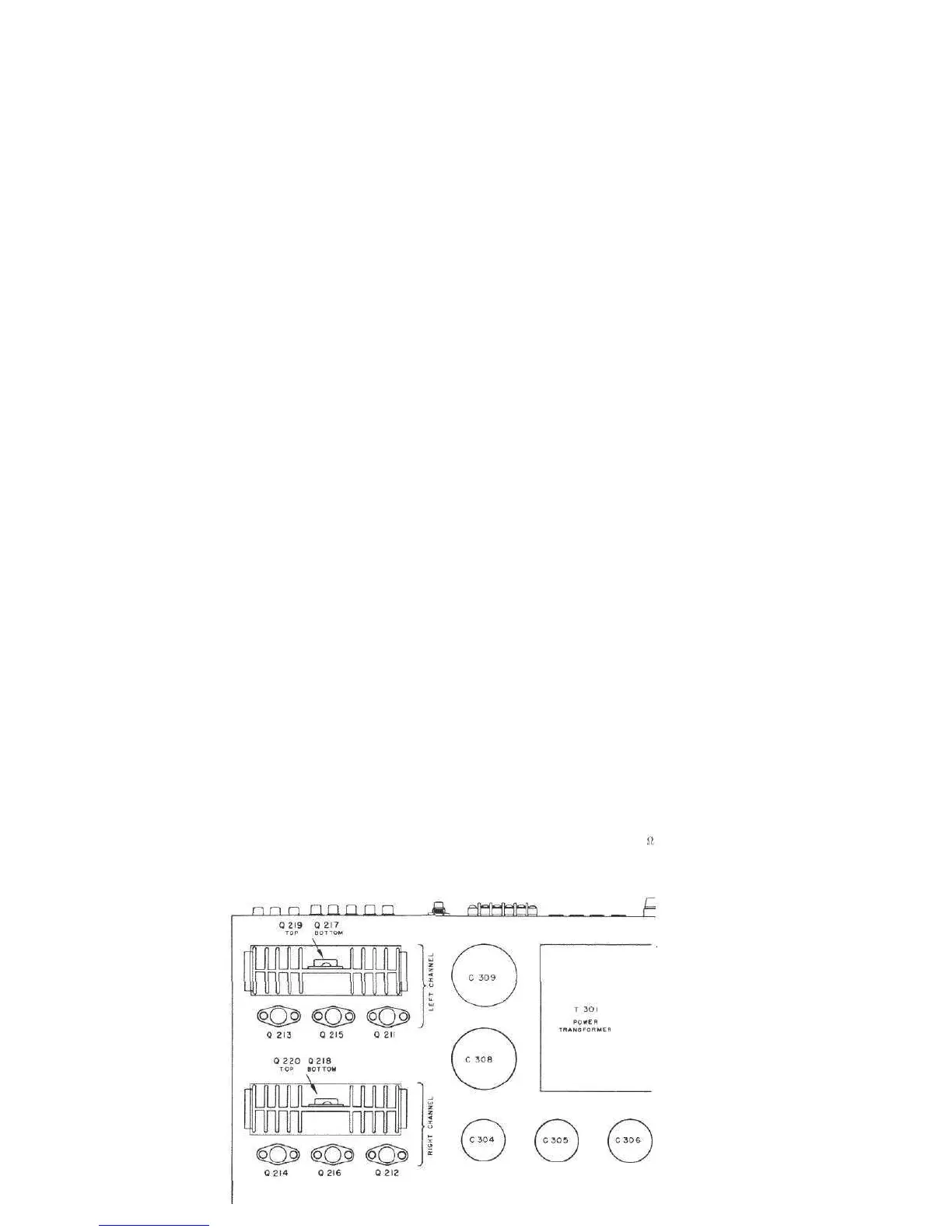
LOCATION OF TRANSISTORS NOT ON PRINTED CIRCUIT BOARDS
 Loading...