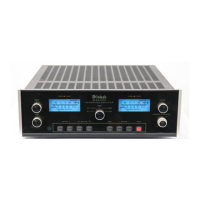
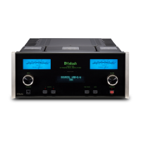
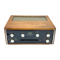
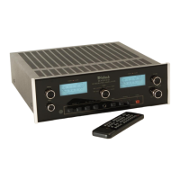
Do you have a question about the McIntosh MA6200 and is the answer not in the manual?
Preparing the cabinet panel and installing mounting hardware for the unit.
Sliding the MA 6200 into the cabinet and securing it using the PANLOC system.
Connecting turntables, tuners, AUX sources, and tape recorders to the amplifier inputs.
Wiring AC power, ground, and loudspeakers to the amplifier.
Using front panel jacks and pushbuttons for tape recording and monitoring.
Adjusting input sources, sound modes, volume, balance, and loudness.
Using tone equalization, headphone jacks, and selecting speaker outputs.
Understanding the Power On button, Power Guard, and other indicator lamps.
Detailed electrical specifications like power output, distortion, and frequency response.
Physical dimensions, finish, weight, and power requirements of the unit.
Explanation of the audio section, preamplifiers, equalizer, and power amplifier stages.
Details on protective circuits, turn-on delay, and the power supply system.
| Power Output | 75 watts per channel into 8 ohms |
|---|---|
| Output Impedance | 8 ohms |
| Frequency Response | 20Hz to 20kHz +0, -0.5dB |
| Input Sensitivity | 2.5mV (MM), 250mV (line) |
| Input Impedance | 47k ohms (phono), 100k ohms (high level) |
