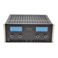
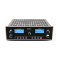
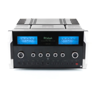
The MA 6200 is designed so it may be used with
two tape recorders. The four left pushbuttons con-
trol the signal output of these recorders. They permit
recordings to be monitored as they are being record-
ed, or copying of tapes from one recorder to another
while listening to a separate program or the play-
back of either recorder.
MONITOR TAPE 1 pushbutton out: The program
source as selected by the INPUT SELECTOR is fed
to the power amplifiers and heard through the
loudspeakers; pushbutton in: Signal from a tape
recorder plugged into INPUTS TAPE 1 is fed to the
power amplifiers and heard through the loud-
speakers.
MONITOR TAPE 2 Pushbutton: Functions similar-
ly to monitor Tape 1. It also controls the program
from a tape recorder plugged into the front panel
TAPE jacks. When a tape recorder is plugged into
the front jacks the tape input circuit is transferred
from the rear TAPE 2 IN jack to the front jack. The
tape recorder plugged into the TAPE 2 IN jack on the
rear panel is automatically disconnected.
TAPE COPY T1 T2 pushbutton in: connects the
output from tape recorder 1 to the input of tape
recorder 2 without affecting the program being
heard from the speakers. In this position a copy of
the program on tape recorder 1 can be made on tape
recorder 2. To monitor the original use MONITOR
TAPE 1 pushbutton and to monitor the copy use
MONITOR TAPE 2 pushbutton.
TAPE COPY T2 T1 pushbutton in: connects the
output from tape recorder 2 to the input of tape
recorder 1 without affecting the program being
heard from the speakers. In this position a copy of
the program on recorder 2 can be made on recorder
1. To monitor the original use MONITOR TAPE 2
pushbutton and to monitor the copy use MONITOR
TAPE 1 pushbutton.
TAPE RECORDER FRONT PANEL CONNECTION
Input and output facilities are available at the
TAPE IN-OUT jacks on the front panel. These front
panel jacks make connections without having to get
at the rear panel. When using the front panel jacks,
the rear TAPE 2 IN jack is automatically discon-
nected. A metal shielded 1/4 inch stereo phone plug
is used for best shielding. Connections follow the in-
dustry standards and are tip: left signal, ring: right
signal, and sleeve: common ground.
SPEAKERS 1, 2 and 3 PUSHBUTTONS
When each of these pushbuttons is pushed in, a
pair of loudspeakers is connected to the power
amplifier outputs. Speaker 1, 2 and 3 may be
selected one at a time, any combination or all at
once.
POWER ON PUSHBUTTON
The POWER ON pushbutton shares AC power
control, through a current detecting switch circuit,
with the AC power switch on a turntable. On the rear
panel the TURNTABLE AUTO/MANUAL switch
selects the mode of operation.
When the switch is in the AUTO position and a
turntable is plugged into one of the green AC power
outlets the AC power to the MA 6200 and to the black
AC power outlets can be controlled by the turntable
on/off switch. When AC power to the turntable is
turned on, automatically the MA 6200 and the SWIT-
CHED black AC power outlets are turned on. The
system will remain on until the turntable is turned
off. The POWER ON pushbutton switch parallels the
automatic turntable power control feature. The
POWER ON pushbutton is used to turn on and off
power when the turntable is not used. The POWER
ON pushbutton must be out or off for the turntable
to control the AC power.
In the MANUAL position only the POWER ON
pushbutton will turn the MA 6200 and black outlet
AC power on and off.
POWER GUARD INDICATOR LAMPS
POWER GUARD assures that the power amplifier
section of the MA 6200 can not be over driven, thus
amplifier output clipping is eliminated. Clipping is
caused when the amplifier is asked to produce more
power output than it can deliver with low distortion.
Amplifiers are capable of delivering large quantities
10
 Loading...
