MA 6100 SCHEMATIC NOTES
1. Unless otherwise specified: Resistance values are in ohms , 1/4 watt,
and 10% tolerance; Capacitance values smaller then 1 are in microfarads
(µF); capacitance values greater than 1 are in picofarads (pF);
inductors are in microhenries ( µH) .
2 . Printed circuit board components are outlined on the schematics by
dotted lines. The circled numbers around the dotted lines correspond
to the numbers on the PC Board layouts.
3 . The heavy lines on the schematics denote the primary signal path.
4. The terminal numbering of rotary switches is for reference only.
5 . All voltages indicated on the schematics are measured under the
fol1ow ing conditions:
6. In units with Serial No's below AE1453; C415 & C416 are 1000pF.
C413 & C414 are 1000µF and C407 & C408 are 470pF.
7. In early export units R429, R430, R447 & R448 are 47
8. In units with Serial No's below AE2557; CI17 and C118 are 12pF.
9. In units with Serial No's below AE2075; R309 is D308. (Mclntosh
Part No. 070-064)
10. In units with Serial No's below AE2122; R211 & R212 are Mclntosh
Part No. 134-354 and R227 & R228 are Mclntosh Part No. 134-253.
11. In units with Serial No's below AE3988; R421 , R422, R423 & R424
are 100 5% 1/2W; R425, R426, R427, & R428 are used; D417,
D418, D419 & D420 are not used; R437 and R438 are used and D4I5
and D416 are not used.
a. Use of an 11 megohm input impedance VTVM.
b. All voltages ±10% with respect to chassis ground.
c. No signal at input terminals.
d. AC
input
at 120
volts,
50/60
Hz.
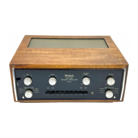
e. Front panel controls at:
Volume Ful1y CW Tape mon. out
Input selector Aux Tape copy out
Mode selector Stereo Filters out
Balance control Zero Phase out
Como Flat Speakers out
Tone controls Flat
 Loading...

