x 8" [20.32 cm], [see Fig. 2]. In addition, a single 3/8"
to 1/2" [1 cm to 1.3 cm] screw hole [see Fig. 2 and
Fig. 3] must be drilled in the shelf to secure the
receiver after installation. The top of the shelf must
be attached flush with the bottom of the custom
panel cutout.
BOTTOM OF PANEL CUTOUT AND
TOP OF SUPPORT SHELF MUST COINCIDE
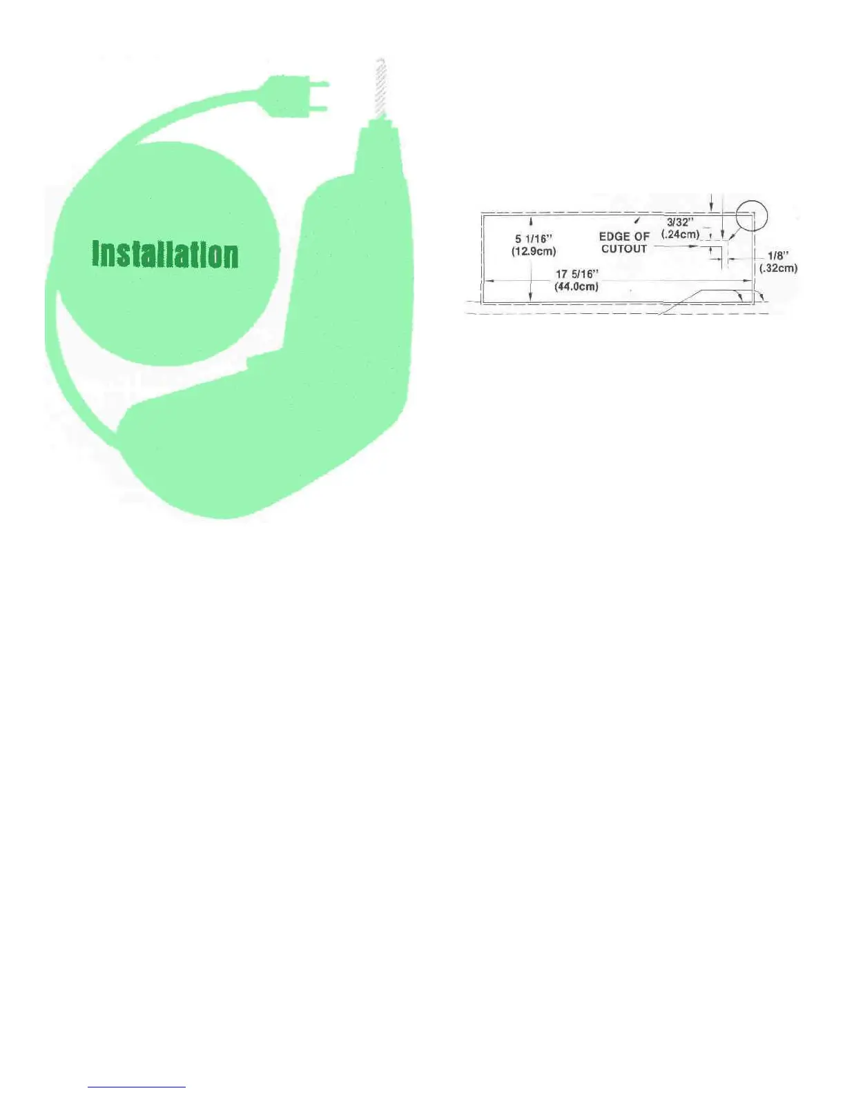
Fig. 1 Custom Cabinet Front Panel Cutout.
The MAC 4100 may be used on a shelf or table top
in the enclosure in which it comes or may be install-
ed in a custom cabinet. In any method of use provide
adequate ventilation.
The trouble-free life of an electronic instrument is
greatly extended by providing sufficient ventilation
to prevent the build-up of high internal temperatures
that cause deterioration. Allow enough clearance so
that cool air can enter at the bottom of the receiver
and be exhaused from the top and rear. With ade-
quate ventilation the instrument can be mounted in
any position.
The MAC 4100 is installed from the front of a
custom cabinet. The desirable space behind the
cabinet panel is 15" [38.1 cm] deep, 18-1/2" [47 cm]
wide, and 6"-[15.2 cm] high. The unit fits an opening
exactly 5-1/16" [12.9 cm] by 17-5/16" [44 cm] wide.
Make this cutout carefully. The receiver's front panel
has a 1/8" [.32 cm] overhang on both sides and a
3/32" (.24 cm) overhang on the top and bottom, [see
Fig.
1].
The weight of the receiver must rest on a shelf in
which there is a ventilation hole cutout 15" [38-1 cm]
Prepare the MAC 4100 for custom mounting by
removing the wood cabinet and feet as follows:
1. Remove 4 screws "A" [see Fig. 4]; two from each
side panel.
2. To remove the enclosure top panel, the receiver's
metal top must be temporarily removed. It is at-
tached to the chassis by 4 screws "B" [see Fig. 4]
installed 2 through the flange on the back and 1
through each of the flanges on the side. Remove
these 4 screws. Save the screws to reinstall the
metal top after removal of the enclosure top
panel.
3. Under the metal top are 5 screws "C" that hold the
enclosure top panel to the metal top [see Fig. 4].
Remove the 5 screws "C" that hold the metal top
to the enclosure top panel.
4. Replace the metal top on the MAC 4100 with the 4
screws "B".
5. On the bottom of the receiver are the 4 plastic feet
held on by screws "D" [see Fig. 4]. Remove these
feet. Do not attempt to remove the 4 plastic but-
ton glides as these rest against the shelf, (see Fig.
2 and 3). At this point the receiver is ready to be
custom installed.
From the front of the cabinet, thread the power
cord through the opening in the cabinet panel and
slide the MAC 4100 in on the shelf. Adjust the posi-
tion to evenly cover the custom panel cutout. Lock
the unit in place with a screw and washer inserted
through the drilled hole in the mounting shelf [see
Fig. 3]. Use a 1-1/4" [3.2 cm] screw for 1/2" [1.3 cm]
shelf or a 1-1/2" [3.8 cm] screw for 3/4 [1.9 cm] shelf.
Do not use longer screws.
EDGE OF 4100 FRONT PANEL
3