9
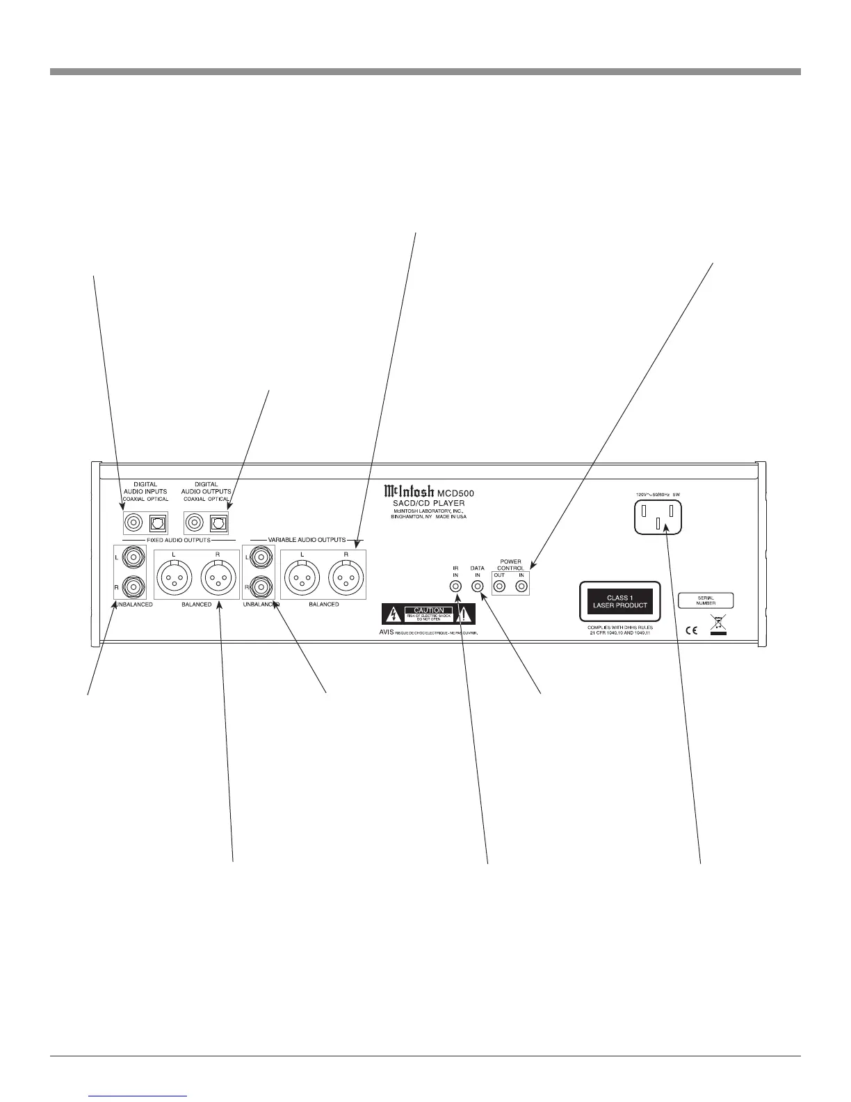
Rear Panel Connections
POWER CONTROL IN
receives turn-on signals
from a McIntosh compo-
nent and POWER CON-
TROL OUT sends turn-on
signals on to another
McIntosh Component
Connect the MCD500
power cord to a live AC
outlet. Refer to informa-
tion on the back panel of
your MCD500 to deter-
mine the correct voltage
for your unit
IR INput for
connecting an IR
Receiver
DATA IN receives
operating data from
a McIntosh Control
Center
COAXIAL AND OPTICAL
DIGITAL AUDIO OUTPUTS
send signals to a Control
Center with a D/A Converter
or a decoder
COAXIAL AND OPTICAL
DIGITAL AUDIO INPUTs
receives a Digital Signal
1
from
an external source component
such as a Disc Player and uses
the MCD500 internal D/A
Converter to decode the signal
into analog audio
BALANCED VARIABLE
level AUDIO OUTPUTS
supply analog audio signals
to connect to Balanced In-
puts of other components
BALANCED FIXED level AUDIO
OUTPUTS supply analog audio signals to
Balanced Inputs of other components
UNBALANCED VARIABLE
level AUDIO OUTPUTS supply
analog audio signals to Unbal-
anced Inputs of other components
UNBALANCED FIXED
level AUDIO OUTPUTS
supply analog audio
signals to Unbalanced In-
puts of other components
1
- For additional information Refer to page 4 “General Information”, note 4.