General Specifications
Power Requirements
100 Volts, 50/60Hz at 65 watts
110 Volts, 50/60Hz at 65 watts
120 Volts, 50/60Hz at 65 watts
220 Volts, 50/60Hz at 65 watts
230 Volts, 50/60Hz at 65 watts
240 Volts, 50/60Hz at 65 watts
NOTE: Refer to the rear panel of the MX135 for the correct
voltage.
Overall Dimensions
Front Panel: 17-1/2 inches (44.5cm) wide, 9-7/16 inches
(23.97cm) high. Depth behind front mounting panel is 19
inches (48.26cm) including clearance for connectors. Panel
clearance required in front of mounting panel is 1-1/8 inches
(2.9cm).
Weight
31.5 pounds (14.3kg) net, 55 pounds (25kg) shipping weight
PERFORMANCE SPECIFICATIONS con’t
MX135
AM Tuner (TM1 option)
Sensitivity
20uV external antenna input
Signal To Noise Ratio
48dB at 30% modulation
58dB at 100% modulation
Harmonic Distortion
0.5% maximum at 50% modulation
Frequency Response
50Hz to 6kHz NRSC
Adjacent Channel Selectivity
45dB minimum IHF
Image Rejection
65dB minimum from 540 to 1600kHz
IF Rejection
80dB minimum
1. The heavy lines on the schematic denote the primary
signal path.
2. Unless otherwise noted, all voltages indicated on the
schematics are measured under the following conditions:
a. AC input at 120 volts, 50/60Hz.
b. All voltages are +/-10% with respect to ground. A
high impedance (10 megaohm) voltmeter must be used.
3. On PC board drawings, Square pad indicates:
a. Polarized Capacitors - Positive
b. Diodes - Cathode
c. Others - Pin 1
4. WARNING
Parts marked with the symbol have critical
characteristics. Use only replacement parts recom-
mended by the manufacturer.
NOTES
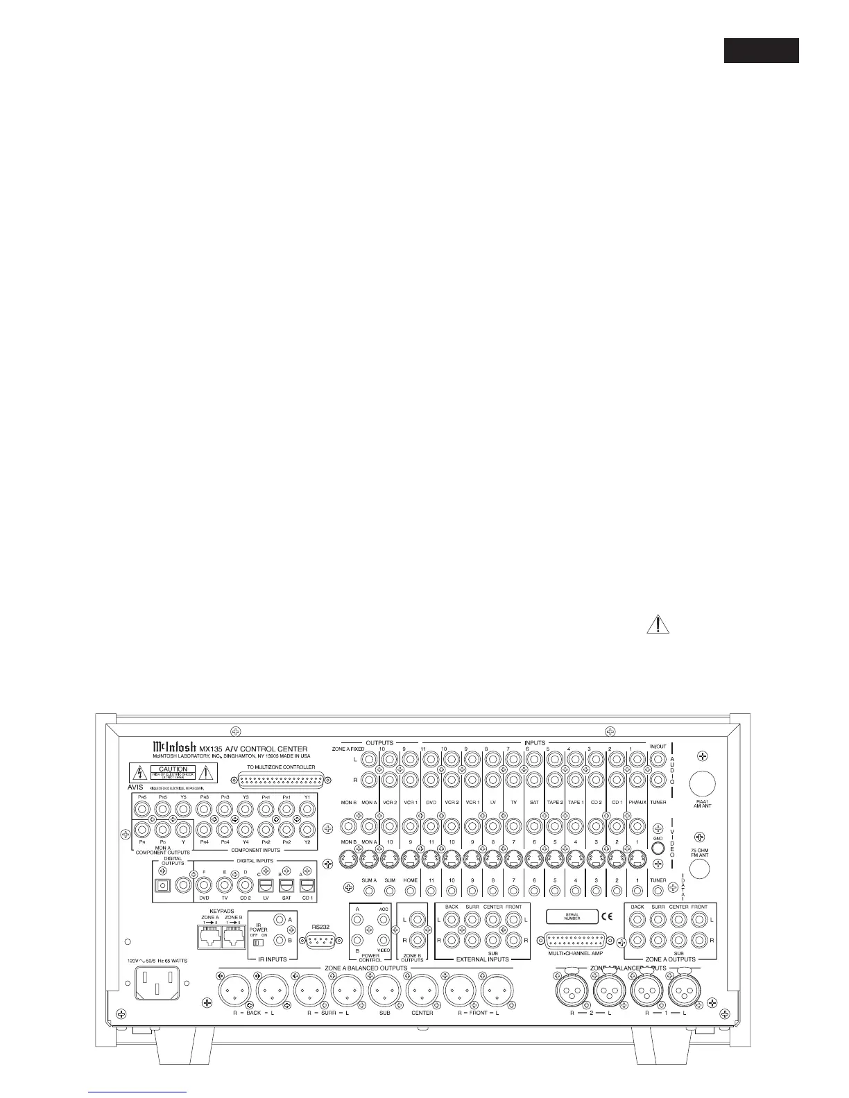
REAR PANEL
3