- 13 -
RPM Measurement
In RPM mode, the testing range is 0~99999RPM, accuracy ±
(0.05% of reading+5). Use the RPM accessory to test the rotation
speed and read the display.
Measurement mode Primary display Secondary display
RPM RPM No display
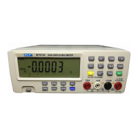
4.9 Temperature Measurement (TEMP)
The measurement of temperature has two modes: normal and Hi.
Measuring range: -50℃~1300℃, -58℉~2372℉
Display: Primary ℃, Secondary ℉
Set the function to “TEMP” position.
Press SELECT button to select Hi or normal mode.
In Hi mode, use K type thermocouple to measure temperature.
Press SELECT again, “Hi” disappears from the display, and the
displayed temperature is internal temperature of the meter.
Connect the black test lead to “COM” terminal and the red test
lead to “VΩ Hz” terminal. Read the display.
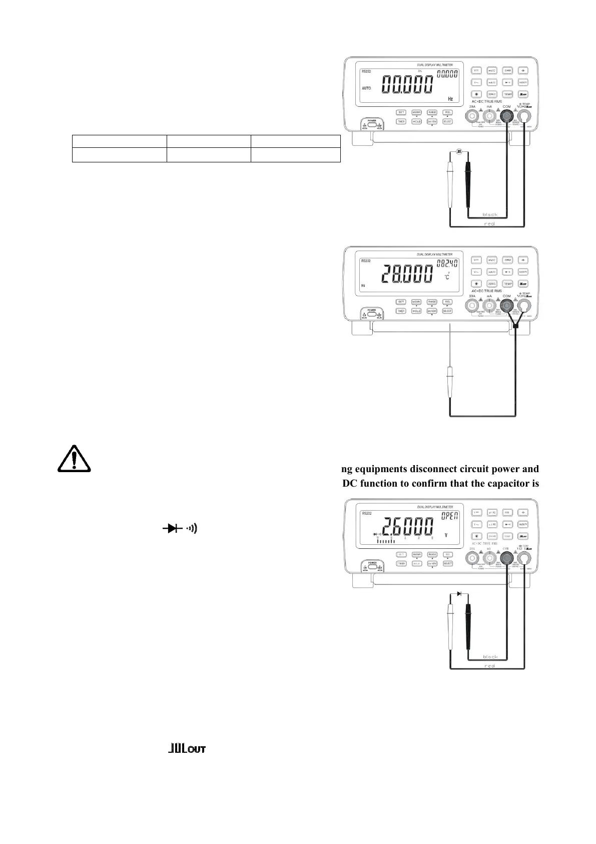
4.10 Diode and Continuity Check
WANRNING: To avoid damage to the meter or the testing equipments disconnect circuit power and
discharge all high voltage capacitors before measuring. Use the DC function to confirm that the capacitor is
discharged.
Set the function to “ ” position.
Connect the black test lead to “COM” terminal and the red
test lead to “VΩ Hz” terminal.
For diode check, touch the red test lead to the positive
polarity of the diode and the black test lead to the negative
polarity. Touch the probes to the test points and read the
display.
For continuity check, the beeper sounds if the resistance
falls below 60Ω.
4.11 Square Wave Output
The meter can be used as a square waveform generator, output the waveform with frequency range of
0.5Hz~5000Hz.
Set the function key to “ ” position. The square waveform will be output on “COM” and “VΩ Hz”
terminals.
The output square waveform is default at 606.1Hz, duty cycle 50%.
 Loading...