- 4 -
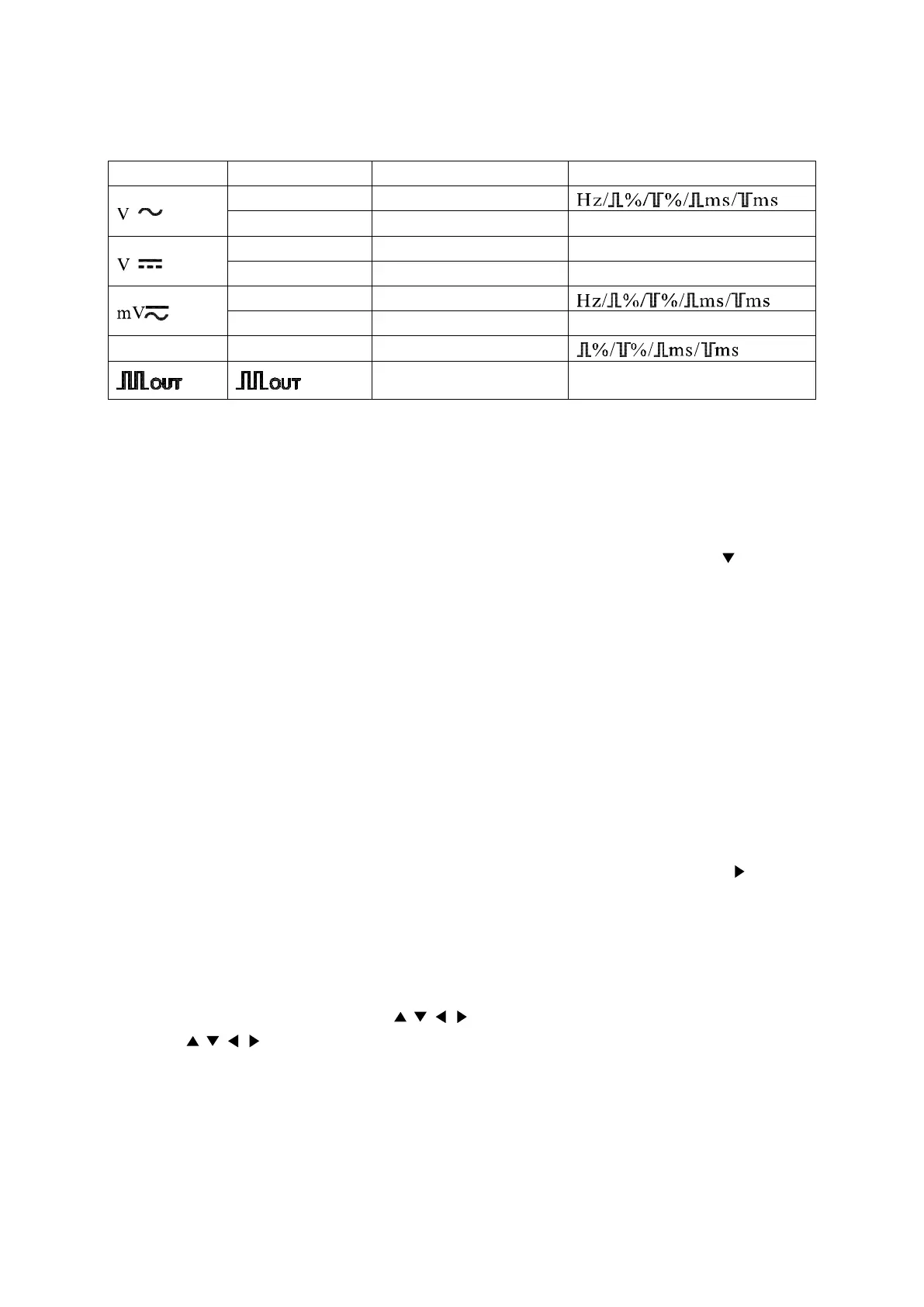
2nd VIEW: Select the secondary display function. In various measuring mode, press 2nd VIEW button to cycle
the displayed data on secondary display. See the follow table:
Function key Measuring mode Primary display Secondary display
ACV+Hz ACV
AC dBm+Hz AC dBm ACV/Hz
(ACV+DCV)+Hz ACV+DCV ACV/Hz
dBm+Hz dBm Hz/ACV/DCV/ACV+DCV
ACmV+Hz ACmV
dBm+Hz dBm Hz/ACmV/DCmV/ACmV+DCmV
Hz/DUTY Hz Hz
Press key
to
change output frequency
Press key
to change
duty value
In square waveform output mode, press 2nd VIEW button to select frequency and trigger the square
waveform at the selected frequency:
0.5000Hz/1.0000Hz/2.0000Hz/10.00Hz/50.000Hz/60.240Hz/74.63Hz/100.00Hz/151.50Hz/200.00Hz/303.00
Hz/606.10Hz/1.2500kHz/1.6660kHz/2.5000kHz/5.0000kHz.
Press this key for at least 2 seconds to return to 606.10Hz, 50% duty output state.
When the SET button is in operation, 2nd VIEW button is using as a moving down button ( ). Pressing this
button moves the setting digit down
REL
△
:
Press this button, the meter enters relative measuring mode and “REL
△
” appears on the LCD display. The
relative measuring function measures the difference between the testing value and the reference value. The
current readings on the secondary display are used as a relative value. The primary display displays the
relative measurement in two modes:
One is: REL
△
=measuring value – Reference value
The other is: REL%= (REL
△
/Reference value) x100% (press SELECT button to select REL
△
or
REL% mode)
Press REL△ button again, the testing value will be used as reference value and displayed on the secondary
display.
While the SET button is in operation, the REL
△
button is used as a moving right button ( ) to move the
setting digit to the right.
Press REL
△
for at least 2 seconds to exits reference mode and return to normal mode.
Set up reference value for measurement:
2. In every reference value, use RANGE button to select a proper range
3. When SET button is in operation, press SELECT button twice to set up reference value for
measurement. At the same time, the is enabled.
4. Use buttons to adjust the reference value.
Press SET button to validate the new setup.
3. Terminal
COM: Common terminal for all measurements
V Ω Hz: Volts, Ohn, Diode, Freq., Temp, and Cap. Measurement and square wave output terminal
MA: Milli ampere current measurement terminal
 Loading...