- 5 -
20A: Ampere current measurement terminal
4. Function Key
: ACV
: DCV
: DC/AC Milli voltage
: Diode & Continuity
Ω : Resistance
DUTY/Hz: Duty/Frequency
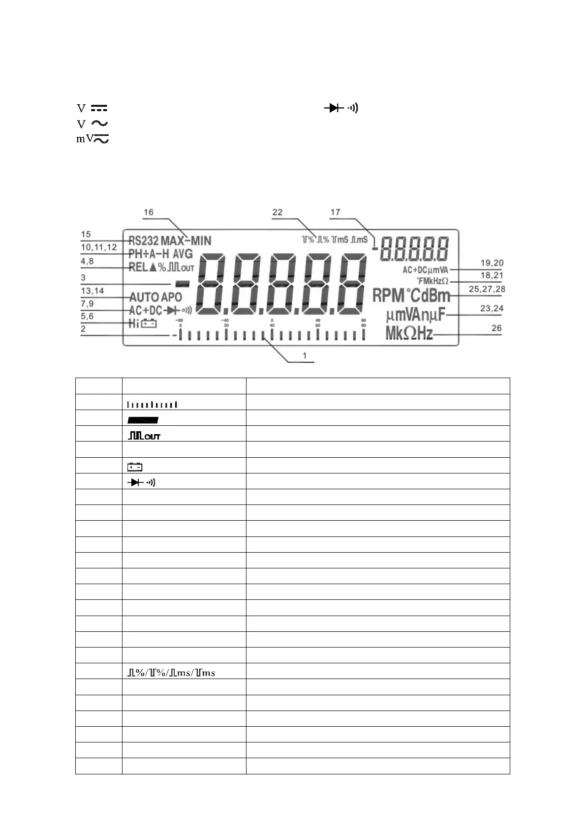
5. LCD Display: The following table gives description of the symbols displayed on the LCD.
Fig.2-3 LCD display
No. Symbol Description
1
Analog bar graph
2, 3, 17
Negative sign
4
Square wave output
5 Hi Hi frequency or thermocouple indicator
6
Low battery
7
Diode/Audible continuity function
8 REL
△
% Relative measurement
9, 19 DC, AC, DC+AC DC, AC, DC+AC voltage or current
10 PH+ PH- +Peak Hold, -Peak Hold
11 A-H Auto Hold
12 AVG Average reading
13 Auto Auto mode
14 APO Auto power off sign
15 RS232 Communication on annunciation
16 MAX/MIN/MAX-MIN MAX Rereading/MIN Reading/MAX-MIN Reading
20 mV/V/mA/A Voltage and current units on secondary display
21 Hz/kHz/MHz/Ω/kΩ/MΩ Frequency and resistance units on secondary display
22
Duty cycle unit and plus width unit
23 nF/μF Capacitance unit
24 mV/V/mA/A Voltage and current units on primary display
25 dBm dBm annunciation
26 Hz/kHz/MHz/Ω/kΩ/MΩ Frequency and resistance units on primary display
27, 18 Temperature units and measurement indicator
28 RPM Round/per minute