IM 778 / Page 19
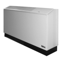
Motorized Valve & Relay for Unit Sizes 007 thru 060
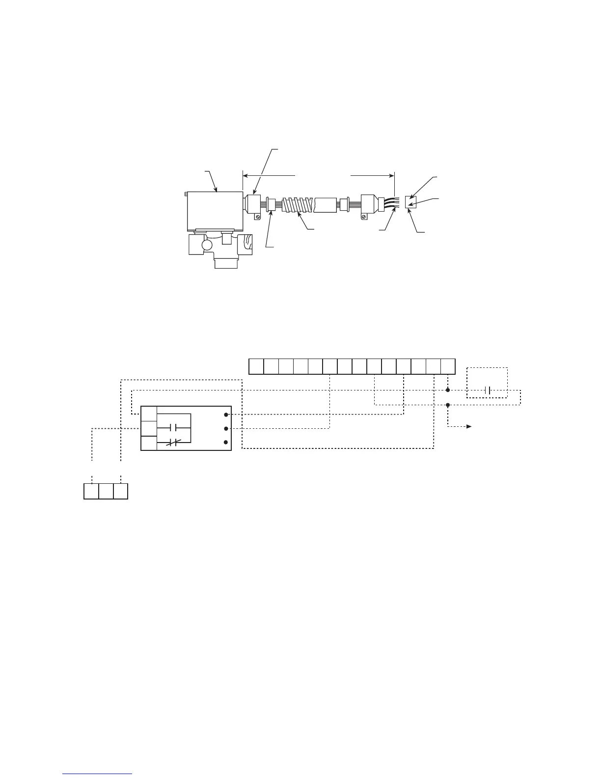
Wired as shown below the motorized valve will open on a
call for compressor operation. Valves for unit sizes 007 to
019 are
1
⁄2" while unit sizes 024 to 060 are
3
⁄4". Other ther-
mostat combinations may be used. Valve and auxiliary
relay(s) are purchased separately.
Note: The wiring shown below can only be used when the “P” ter-
minal is not being used as a pump restart signal to other equip-
ment. If the “P” terminal must be used as a pump restart signal to
other equipment, then wire the auxiliary relay’s yellow wire to
“Y1”, white wire to “W1”, and orange wire to “C”, then the valve
will open on a call for occupied heating or cooling from the
thermostat.
P/N 060977401 - 1/2" Motorized Valve Kit
P/N 060977301 - 3/4" Motorized Valve Kit
P/N 859004354 - Valve Relay Kit
 Loading...