EasyManua.ls Logo

McQuay LMS - User Manual

McQuay LMS
24 pages
Print Icon
To Next Page IconTo Next Page
Loading...
Installation & Maintenance Data IM 439-15
Group: WSHP
Part Number: 106581103
Date: June 2006
Large Vertical Water Source Heat Pumps
6 thru 25 Tons
Models LDD, LDE, LDL, LDS, LME, LMH, LML, LMS
©2006 McQuay International
®
Question and Answer IconNeed help?

Do you have a question about the McQuay LMS and is the answer not in the manual?

Summary

Model Nomenclature

Design Series

Explains the designation for different design series of the units.

Nominal Capacity

Details the numerical codes for unit capacities in BTUs.

Coil Options

Lists available coil options for unit configuration.

Voltage

Specifies voltage codes for unit power supply.

McQuay Product Identifiers

Provides a key to model codes based on features and range.

Transportation and Storage

Unit Location

Guidance on selecting and preparing the installation site for optimal performance and service.

Unit Arrangement

Filter Access

Vibration Isolation

Air Balancing

Adjustment

Step-by-step guide for adjusting variable pitch motor sheaves for proper airflow.

Ductwork and Attenuation

Ventilation Air

Optional Duct Collar and Filter Rack

Piping

Condensate Disposal

Proper methods for installing condensate drain piping and traps.

Cleaning and Flushing System

Cleaning and Flushing System (Continued)

Start-up

Cooling Operation Checks

Procedures and checks for successful unit operation in cooling mode.

Heating Operation Checks

Procedures and checks for successful unit operation in heating mode.

Common Start-up Issues

Troubleshooting common problems encountered during initial unit startup.

Operating Limits

Air and Water Limits

Specifies the acceptable ambient and water temperature ranges for operation.

Water Enthalpy Specifications

Details water enthalpy values for different operating conditions.

Electrical Data

General Electrical Requirements

Guidelines for power supply, wiring, and fusing.

Minimum and Maximum Voltage

Permissible voltage ranges for unit operation.

Typical Wiring Diagrams

Single Compressor Unit Diagram

A detailed wiring diagram for a single compressor Mark IV/AC unit.

Dual Compressor Unit Wiring Diagram

MicroTech Unit Wiring Diagrams

Single Compressor Unit Diagram

Wiring schematic for a single compressor MicroTech unit.

MicroTech Controller Terminal Connections

Details on connecting wires to the MicroTech controller terminals.

MicroTech Unit Wiring Diagrams

Dual Compressor Unit Diagram

Wiring schematic for a dual compressor MicroTech unit.

Auxiliary Module Connections

Details on connecting the auxiliary module on MicroTech units.

Unit Operation

Mark IV;AC Control System Overview

Specific operational features and functions of Mark IV/AC control systems.

Mark IV;AC Sequence of Operation

Detailed sequence of operations for Mark IV/AC units.

Mark IV;AC Terminal Strip Functions

Description of the functions of each terminal on the Mark IV/AC board.

LED Status and Fault Output Status

Board Status LED Indicators

Details the meaning of LED colors and patterns for different modes.

Fault Handling Features

Information on remote reset, fault retry, and general input usage.

Thermostat Connection Diagrams

Programmable Thermostat Wiring

Wiring diagrams for connecting a 7-day programmable thermostat.

Non-Programmable Thermostat Wiring

Wiring diagrams for connecting a non-programmable thermostat.

Thermostat Connections for Larger Units

Programmable Thermostat (2 Circuits)

Wiring for programmable thermostats on dual-circuit units.

Non-Programmable Thermostat (2 Circuits)

Wiring for non-programmable thermostats on dual-circuit units.

Optional Remote Sensor Installation

Instructions for installing an optional remote temperature sensor.

Miscellaneous Options on Mark IV Units

Pump Restart Relay Kit Installation

Details the pump restart relay option and its wiring.

Motorized Valve & Relay Options

Motorized Valve Installation Guide

Illustrates the typical installation of a motorized valve assembly.

Boilerless System Kit (BSK)

BSK Wiring and Operation Guide

Explains how the BSK interacts with the Mark IV/AC board for duct heater control.

Auxiliary Relay

Auxiliary Relay Wiring Examples

Shows various ways to connect the auxiliary relay for different functions.

Field Installed Options for MicroTech Units

Configurable Output Signal Types

Lists and explains the four types of output control signals available.

Auxiliary Module Kit Installation

Information on the auxiliary module for additional output signals.

Troubleshooting Water Source Heat Pump

Unit Troubleshooting Flowchart

A visual guide to identify and resolve unit operational issues.

Maintenance Procedures

Filter Changes and Lubrication

Recommendations for filter replacement and fan motor lubrication.

Condensate Drain Pan Maintenance

Procedures for checking and cleaning the condensate drain pan.

Performance Data Recording

Importance of recording and comparing performance data.

Understanding Periodic Lockouts

Common causes for unit lockouts and protective shutdowns.

Warranty Information

Overview

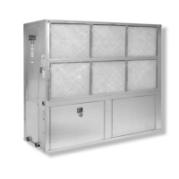
This document describes the installation and maintenance of Large Vertical Water Source Heat Pumps, ranging from 6 to 25 tons. These units are designed for indoor installation and are available in various models including LDD, LDE, LDL, LDS, LME, LMH, LML, and LMS.

Function Description

The Large Vertical Water Source Heat Pumps are designed to provide heating and cooling for building spaces. Each unit incorporates a printed circuit board control system, with low voltage output from the terminal strip always at 24 volts DC. The control board also supplies 24 volts AC power to terminals C and R. These units are specifically designed to operate with a 24-volt mercury bulb type wall thermostat or a microelectronic wall thermostat selected by the manufacturer.

Single compressor units utilize a single Mark IV/AC circuit board, while dual compressor units feature two Mark IV/AC circuit boards. The refrigerant circuits in dual compressor units operate independently, allowing for total independent operation of each circuit. The Mark IV/AC circuit board includes several built-in features such as random start, compressor time delay, night setback, load shed, shutdown, condensate overflow protection, defrost cycle, brownout, and LED/fault outputs.

The low voltage terminal strip on each board is configured such that R-G energizes the fan, R-Y1 energizes the compressor for cooling, and R-W1 energizes the compressor and reversing valve for heating. The reversing valve is energized in the heating mode. A fan interlock circuit ensures the fan energizes whenever the compressor is on, even if the thermostat logic fails.

A lockout circuit on the Mark IV/AC control board stops compressor operation if any safety switches (high pressure, low pressure, or low temperature) open. If the low temperature switch opens, the unit enters cooling mode for 60 seconds to defrost the water-to-refrigerant heat exchanger before locking out the compressor. If the condensate sensor detects a filled drain pan, compressor operation is suspended only in cooling mode. The unit can be reset by opening and closing the disconnect switch on the main power supply. The Mark IV/AC control board also provides a fault output signal to an LED on a wall thermostat, indicating various fault conditions.

The system supports night setback operation, activated by a "grounded" signal to the "U" terminal on the low voltage terminal strip. This shuts off the fan and places the unit under control from the night setback terminal on the thermostat. For dual compressor units, W2 on single compressor and W3 on dual compressor units are used for day heating and cooling operation, with load shed and shutdown operations activated by a "grounded" signal to the "L" and "E" terminals, respectively.

The P and C terminals on the Mark IV/AC board are used for pump restart, passing a voltage signal when the unit's compressor is on. This signal can be detected by a Pump Restart Relay board to control heat pump loop circulation pumps, especially during unoccupied periods.

MicroTech 2000 units offer up to four configurable outputs for various control signals:

  • Scheduled Output: These outputs can be assigned to one of 32 schedules, energizing when the schedule is occupied and de-energizing when unoccupied. Useful for controlling lights, etc.
  • Auxiliary Heat (Skin Heat): Used when a Loop Water Controller (LWC) provides loop water temperature information. The output energizes for electric heat when loop water temperature is inappropriate for heat pump heating.
  • Fresh Air Damper: Energizes when the unit fan is on and de-energizes when the fan is off, controlling a remote fresh air damper.
  • Motorized Water Valve: Controls a motorized water valve to stop or divert flow from the WSHP when compressor operation is not needed, energizing when the compressor is required.

Important Technical Specifications

  • Capacity: 6 thru 25 Tons.
  • Voltage: Available in 208-60-3, 230-60-3, 460-60-3, 575-60-3, and 380-50-3.
  • Minimum and Maximum Voltage Ranges:
    • 208/60/3: Min. 187 volts, Max. 229 volts
    • 230/60/3: Min. 207 volts, Max. 253 volts
    • 460/60/3: Min. 414 volts, Max. 506 volts
    • 575/60/3: Min. 515 volts, Max. 632 volts
    • 380/50/3: Min. 360 volts, Max. 418 volts
  • Three-phase system unbalance: Should not exceed 2%.
  • Air and Water Limits (Cooling/Heating):
    • Min. Ambient Air: 40°F/5°C (Cooling/Heating)
    • Normal Ambient Air: 80°F/27°C (Cooling), 70°F/21°C (Heating)
    • Max. Ambient Air: 100°F/38°C (Cooling), 85°F/29°C (Heating)
    • Min. Ent. Air: 50°F/10°C (Cooling), 40°F/5°C (Heating)
    • Normal Ent. Air, db/wb: 80/67°F (Cooling), 70°F (Heating)
    • Max. Ent. Air, db/wb: 100/83°F (Cooling), 80°F (Heating)
    • Min. Ent. Water: 55°F/13°C (Cooling/Heating), 40°F/5°C (Cooling/Heating)
    • Normal Ent. Water: 85°F/29°C (Cooling), 70°F/21°C (Heating)
    • Max. Ent. Water: 110°F/43°C (Cooling), 90°F/32°C (Heating)
  • Piping: Steel, copper, or PVC. Condensate disposal piping requires a trap and must be pitched away from the unit at not less than 1/4" per foot (21 mm per meter).
  • Filter Size: Units are shipped with a filter bracket for side filter removal. Optional 2" (51 mm) filter rack available.
  • Vibration Isolation: Recommended to be mounted on vibration isolators. Holes are provided in the bottom panel for connection. Four white isolators for single compressor units, six green isolators for dual compressor units.
  • Ductwork: Discharge ductwork is normally used. Return air ductwork may require field installation of a return air duct collar. All ductwork should conform to ASHRAE Systems Guide standards.

Usage Features

  • Unit Location: Requires sufficient clearance for filter removal, access panels, water, electrical, and duct connections. A minimum of 24" (610 mm) clearance is needed on the return air, control box, and piping sides, with 36" (914 mm) recommended for easier serviceability. 12" (305 mm) clearance on Side A for shaft removal, and 6" (152 mm) on Side B for top panel screws.
  • Unit Arrangement: Two fan discharges and piping arrangements are available (right-hand or left-hand). The main control panel is in the center, lower section, under the return air filter.
  • Air Balancing: Units are supplied with a variable pitch motor sheave for airflow adjustment. The sheave should be set at the low end of the rpm range for required airflow. After balancing, the variable pitch sheave should be replaced with a properly sized fixed sheave for longer belt and bearing life and vibration-free operation.
  • System Start-up:
    1. Open all valves and turn on power.
    2. Set thermostat to "Fan Only" or "Off" at system and "On" at fan switch.
    3. Reset variable pitch motor sheaves for correct airflow.
    4. Set thermostat to "Cool" (or coolest position for automatic changeover). Check discharge grilles for cool air and measure water temperature difference (10°F to 14°F or 5°C to 8°C).
    5. Set thermostat to "Heat" (or warmest selection for automatic changeover). Check for warm air delivery and measure air temperature rise (should not exceed 35°F/19°C).
  • Optional Remote Sensor (P/N 667720401): Can be installed by connecting two-strand shielded wire between the remote sensor and thermostat. The main sensor on the thermostat (R12) must be disabled by cutting it from the circuit board.
  • Motorized Valve & Relay: Used to open the valve on a call for compressor operation. These are power-open, power-close valves. The auxiliary relay's yellow wire connects to Y1, white to W1, and orange to C, allowing the valve to open on a call for occupied heating or cooling from the thermostat.
  • Boilerless System Kit (BSK): Provides capability to control a remote duct heater with low voltage control circuit. The BSK board's contacts (1, 2, and 3) control the remote duct heater, with N.O. contacts closing on a call for heat. POT1 allows manual adjustment of the water temperature setpoint (43°F to 60°F). A Normal/Override switch manually forces electric heat instead of heat pump heat.

Maintenance Features

  • Filter Changes: Required at regular intervals. Check filters every 60 days for the first year. Change if light cannot be seen through the filter when held up to sunlight or a bright light.
  • Fan Motor Lubrication: Perform according to the instruction label on the conditioner, using non-detergent electric motor oil. New fan motors are pre-lubricated for the first year.
  • Condensate Drain Pan: Check and clean annually.
  • Performance Monitoring: Record volts, amps, and water temperature differences (heating and cooling) regularly. Compare logged data with start-up and annual data to assess equipment condition.
  • Troubleshooting Lockouts: Periodic lockouts usually indicate air or water problems. Check for dirt in the water system, water flow rates, and water temperatures. If lockouts occur after night setback, entering air below machine limits may be the cause.
  • System Cleaning and Flushing: Before initial operation, the water circulating system must be cleaned and flushed of construction dirt and debris. If equipped with shutoff valves, supply and return runouts must be connected together to prevent dirt from entering the unit.
  • Water Treatment: After flushing, refill the system with clean water. Test for acidity and treat as required to maintain a slightly alkaline pH (7.5 to 8.5). Commercial grade anti-freeze designed for HVAC systems can be added.
  • Troubleshooting Guide: A comprehensive guide is provided for diagnosing issues such as "Neither Fan, nor Compressor Runs," "Compressor runs in short cycle," "Fan operates, Compressor does not," and "Insufficient cooling or heating." This guide helps identify problems like loose wiring, blown fuses, faulty thermostats, incorrect airflow, dirty filters, low refrigerant charge, and compressor issues.

McQuay LMS Specifications

General IconGeneral
BrandMcQuay
ModelLMS
CategoryHeat Pump
LanguageEnglish

Related product manuals